PCB Assembly Quote

Description for this block. Use this space for describing your block. Any text will do. Description for this block. You can use this space for describing your block.

What do you need to get a quote on a PCB assembly? This is a great question and often a source of confusion. There are four basic documents and exactly how they are transmitted depends on your company’s tools; we can work together to figure out what best fits your circumstance. Here we’ll explain what documents are necessary, as well as what information they should all contain, and their role in the quote process.
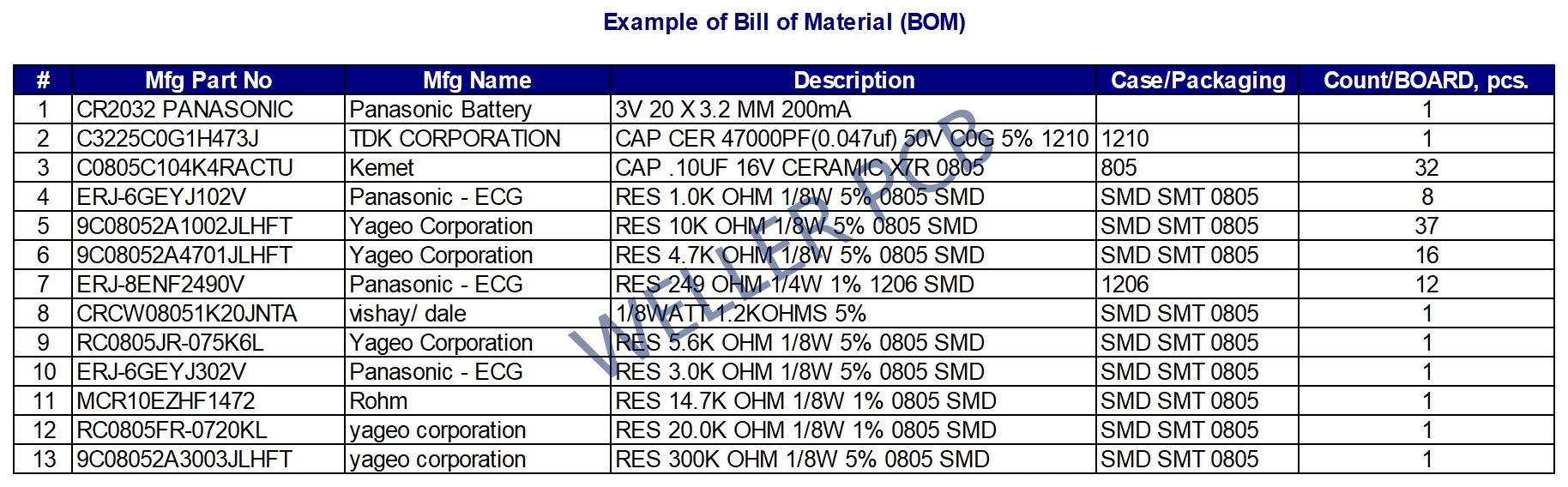
Inquiry sheet along with the PCB fabrication specification. PCB specification sheet Template

PCB files for manufacturing: P-CAD, Gerber data (,ODB++ files,or Gerber RS-274X format), Altium files (please inform us the Altium Designer version you used once you will send us Altium files);

Bill of Material (BOM), which should include complete model names & brands at least for active parts like ICs and for connectors. For passive parts please provide at least the specification like: resistance/ capacity, voltage, tolerance and code for size of the part – like “0402”(Excel files is preferred than .txt or .pdf files).

PCB specification: order sheet with the specification of PCB (the same data as PCB specification sheet);

PCB manufacturing files: P-CAD, Gerber data (,ODB++ files,or Gerber RS-274X format), Altium files (please inform us the Altium Designer version you used once you will send us Altium files);

BOM list: bill of material (BOM) in excel format (Excel format preferred than .txt or .pdf format);

PCBA place list: Assembly places list including model name of parts with marking of assembly place each as stipulated in notation print (Template of assembly places List)

PNP files (pick and place file): Coordinates And Orientation (CAO) List: of pairs (“X” & “Y” ) of coordinates of the centre of each part, where to be located on the board), marking if topside or bottom side assembly, orientation of parts in degrees (0 / 90 / 180 / 270 degree) (template of PCBA CAO List);

Silkscreen drawing: which will show the orentiation and direction of polarity feature components and ICs (PCB assembly drawing template).

Instruction for PCBA requested test (Template of instruction for PCBA e-test).

Schematic drawing: This would be helpful to us as a reference once some polarity components sign missed your silkscreen files

In Certain Cases We Might Need Following Additionally:

Drawings for some fabricated parts (e.g. connectors);

Net List and Node Count (if functional test required);

Specification Sheet for dimensional Data of non-standard components;

Reference pictures from historical production, if any

Contact WELLER Now With Your PCB Assembly Needs