
What is CTI (Comparative Tracking Index) of the PCB base material?
With the increasing miniaturization and highly integrated development of electronic products, the increased packing density of components are more and more assembled on the printed circuit boards, which requests increasingly smaller conductor tracks spacing. Hence, the CTI (Comparative Tracking Index) / PTI (Proof Tracking Index) value in the PCB base material data sheets gets more important. This is the index for tracking resistance.
What Does the CTI Mean?
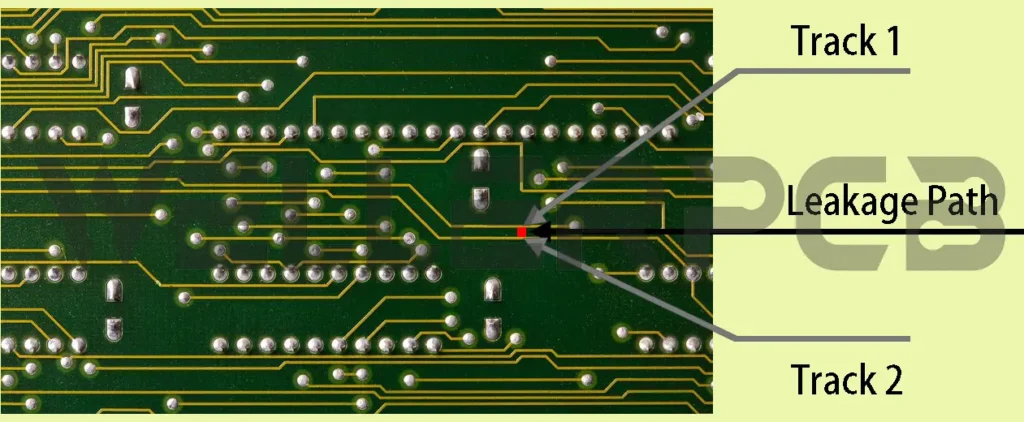
CTI is short for Comparative Tracking Index, means the maximum voltage measured in volts to verify the electrical breakdown properties of an insulating material that used in the electronic devices. At this voltage the specific material can withstands 50 drops of contaminated water without any tracking. Tracking means the conductive paths (or called PCB current leakage path) formed due to heat, electrical tress, humidity and contamination. Therefore, it is also called as PCB leakage current resistance.
A rigid or flex PCB is utilized to provide mechanical support and to interface electrical components electronically through utilizing conductive path, the signal routes or tracks etched from copper foils covered onto a laminated fabric substrate sheet. Comparative tracking index is the printed circuit board materials electrical ability of insulating and unneeded current to have flowing access on the PCB board between circuit traces. It can be interpreted as tracking resistance offered by circuit board track against the current flowing. The high density of components placed on the circuit board the higher its overall packing density, which leads to the smaller circuit trace space.
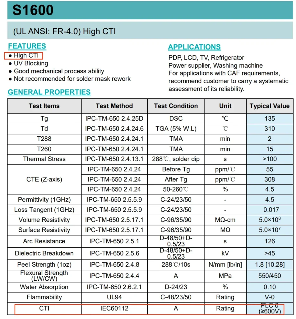
Therefore, if you start to design an electronic devices for some specific application as daily home life: such as washing machine which request PCB base material with CTI≥600V, the CTI / PTI value in the PCB base material is of prime importance. These values help to deduce the overall PCB tracking resistance to eliminate potential risk of current leakage.
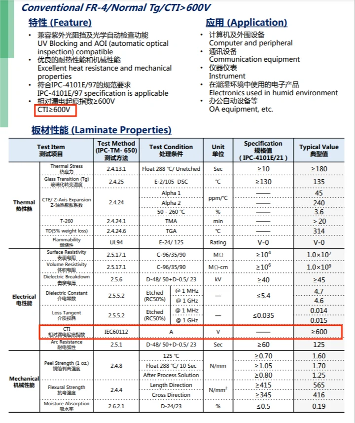
The higher CTI value, the more resistant the material is. The typical CTI value for FR4 base material is 175V and goes up to 600V on some special materials. The CTI / PTI value is determined using standard test methods, generally it is tested under IPC-TM- 650.
These CTI values present an estimation for short-circuit or leakage while circuit trace spacing becomes small due to the increased number of electronics components on the circuit board. As per IEC 60112 standard, the smaller CTI grade (I, II, IIIa, IIIb) substrate offers good resistance to the electrical breakdown. Obviously, CTI is a critical number while selecting a PCB base material for a special electrical application. Normal FR-4 ranges from 175 to 600V. Normally, the typical CTI values are specified by IEC 60112 in below according to the result of the test method on the specific material.
CTI grade per IEC 60112
| Grade | Comparative Tracking Index (CTI) in Volts | Laminate reference |
| I | CTI≥600V | Shengyi S1600, KB-6160C |
| II | 400 <= CTI < 600 | |
| IIIA | 175 <= CTI < 400 | KB-6160F CTI 175V LOW CTE UV-blocking; KB-6160 CIT 175V UV-blocking; KB-6160A CIT 175V UV-blocking |
| IIIB | 100 <= CTI < 175 | Most FR1 base material can meet this value |
Understanding CTI and PCB Circuit Traces
When two circuit traces on the PCB run in parallel sequence, these parallel traces should be able to carry current without any problems and the PCB dielectric material should not breakdown at any time. There is less chance of dielectric breaking down or direct short between traces. The dielectric is to ensure the resistance existing in the two traces. One of the primary reasons that leakage current exist in two wires is due to the impurities forming between wires, voltage applied, temperature, humidity, and other environmental conditions.
CTI value presents one PCB insulating base material’s susceptibility to the electrical breakdown. Intuitively, CTI is that voltage, breakdown occurs after 50 drops of 0.1 percent ammonium chloride solution have fallen on the PCB base material.
CTI Value and Creepage Distance
Creepage distance refers to the shortest path between two PCB traces measured along the surface of the insulating material, or the shortest path between the conductive component and the protective interface of the equipment. This distance depends on the effective value of the working voltage and the CT value of the insulation base material. The distance measured along the insulation surface includes the charged area caused by the insulation material around the conductor. In practical applications, the creepage distance cannot be less than the electrical gap at any time. The creepage value will differ from different CTI value of the PCB base material. If the base material’s CTI value is higher, then it’s minimum creepage value is required. In short, high a CTI value indicates closeness between the PCB circuit traces.
Contact us freely when you design a project which require a high CTI value but determined by budgetary cost. Our engineer will recommend a best option for your reference.