How to Export Gerber Files from Altium Designer
Altium designer is a leading printed circuit board design software that connect PCB designers rather than PCB manufacturers. The initial files generated from Altium is in the format of .pcbdoc, which is only a design files for circuit route but not useful for PCB manufacturers who need the files that meet computer aided manufacturing, such as Gerber files. So, when you finish your PCB design and be ready for release it to the PCB suppliers you need to convert them the Gerber files from Altium.
PCB Design Rule Check
In order to have the PCB manufacturer used correct file to produce the circuit boards, it is necessary that make sure you run PCB design rule check (Tools->Design Rule Check…) before you generate Gerber files and send them out. DRC process usually makes sure that your circuit board doesn’t exceed the PCB manufacturer’s production abilities.
Our PCB manufacturing capabilities are outlined at the home page of /technology/pcb-capability/, please using Design Rule Wizard to modify the rules accordingly.
Double confirm that there are no errors or debugs in your circuit routing. If there are errors, you need to fix them before you can continue to generate Gerber files.

Generate PCB Gerber File
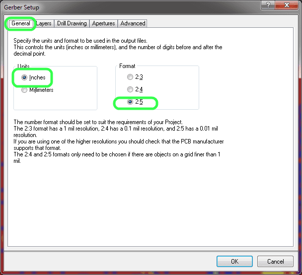
In PCB view, select File -> Fabrication Output -> Gerber files. Then in the popup dialog, select General tab, set Unit to inch and format to 2:5:
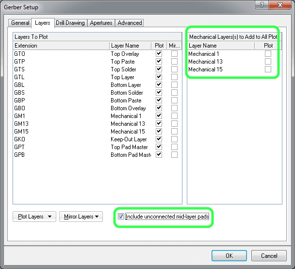
In Layers tab, select “Used On” for the Plot Layers drop down, select “All OFF” for Mirror layers. Check “include unconnected mid-layer pads”, and uncheck “Mechanical layers to Add to All plot”:
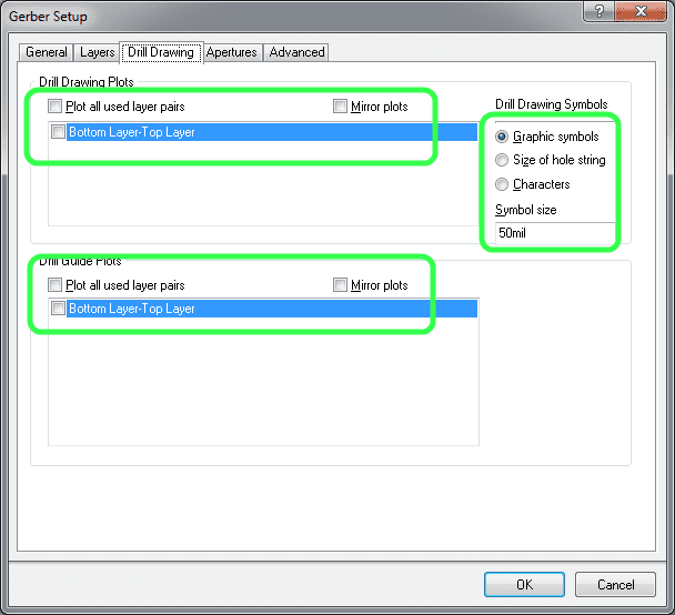
In the Drill Drawing tab, deselect all check boxes, and select Graphic Symbols:
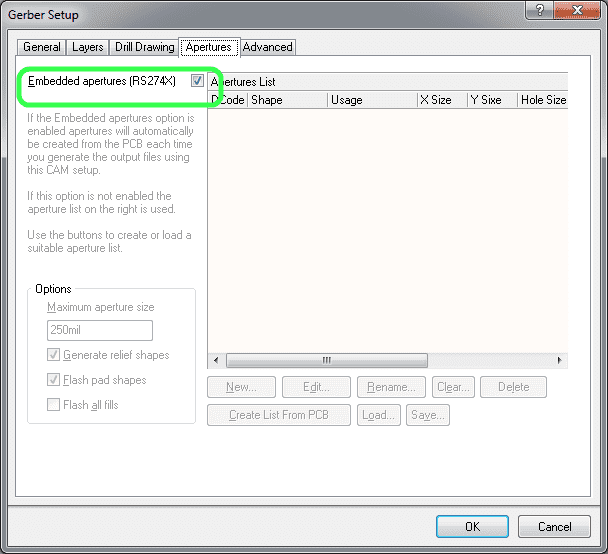
In Apertures tab, make sure RS274X is selected:
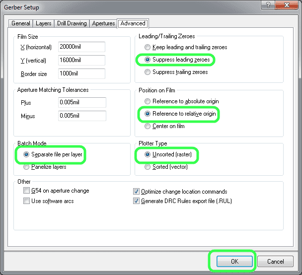
In advanced tab, select “Separate file per layer” for batch mode option. Also select “Suppress leading zeros” for Leading/Trailing Zeros, select “Reference to relative origin” for position on film and select “Unsorted” for plotter type, then click OK:
After a few seconds, Gerber files are generated. You don’t need to save the generate CAM file, just close it.
Generate NC Drill File
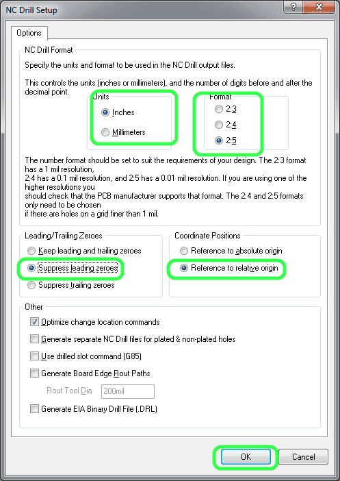
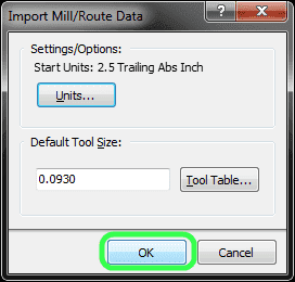
Then in the PCB view, select File -> Fabrication Outputs -> NC Drill Files, in the NC Drill Setup dialog, select “Inches” for Units, “2:5” for Format, “Suppress leading zeros” for Leading/Trailing Zeros and “Reference to relative origin” for Coordinate Positions, then click OK:
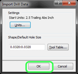
Click “OK”:
Click “OK”:
Package Gerber File
Altium saves all generated Gerber and NC Drill files in the “Project output folder”, usually it is in the same folder as your PCB project folder. Rename the project output folder to something meaningful so you know what it is.
Then zip all files in the output folder and send to us for PCB fabrication.
The following summarizes the Altium Gerber file extensions:
| GTL—Top layer GBL—Bottom layer GTO—Top overlay GBO—Bottom overlay GTP—Top paste GBP—Bottom paste GTS—Top solder GBS—Bottom solder G1 —Midlayer 1 G2 —Midlayer 2 … GP1—Internal plane 1 GP2—Internal plane 2 … GM1—Mechanical 1 GM2—Mechanical 2 … GKO—Keepout layer GG1—Drill guide GD1—Drill drawing GPT—Top pad master GPB—Bottom pad master |