
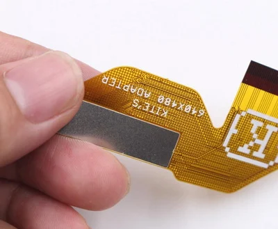
Most experienced PCB designers are expert in rigid PCB design but not good at flex circuit board design, such as stiffeners for flex PCB board.

Firstly, the PCB designers should have complete knowledge about stiffeners, such as:
How to correctly design stiffeners for a flex circuit board
In the flex PCB assembly, stiffeners are a common and important requirement in many types of flex circuits designs. Stiffeners provide a necessary mechanical function for the flexible zone and are not part of the electrical requirements of the overall part (This is not important but necessary part).
So, to have a best stiffeners design, it is necessary for designer to specify:
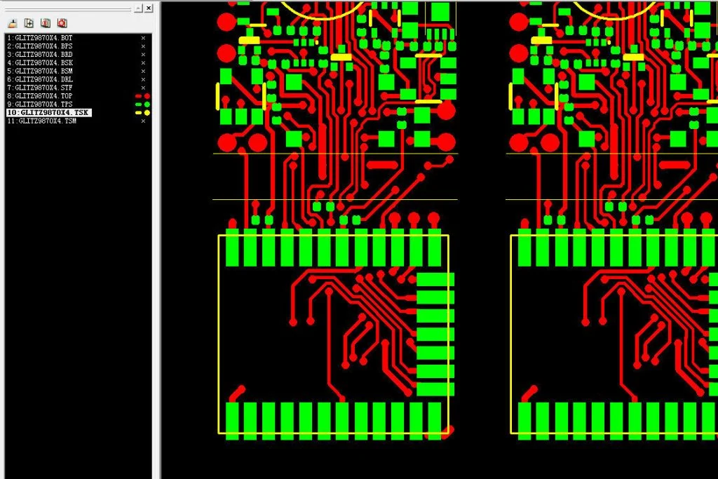
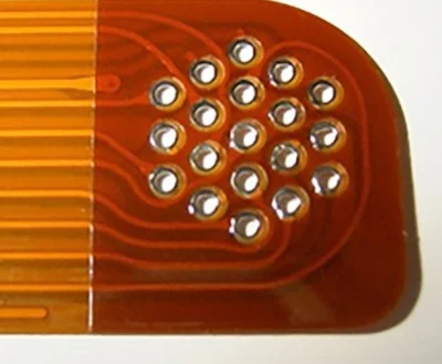
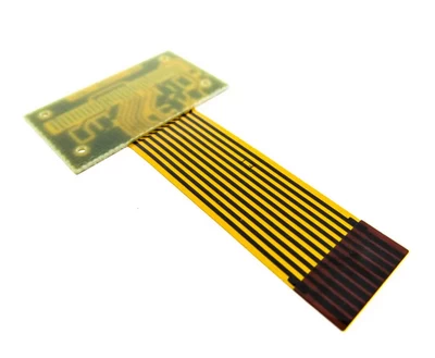
Above 3 pictures is the exact design from customer (picture can be magnified by clicking):
The picture 1 is from the top circuit side review, which we can see there are some SMD components placed on the bottom side (back side).
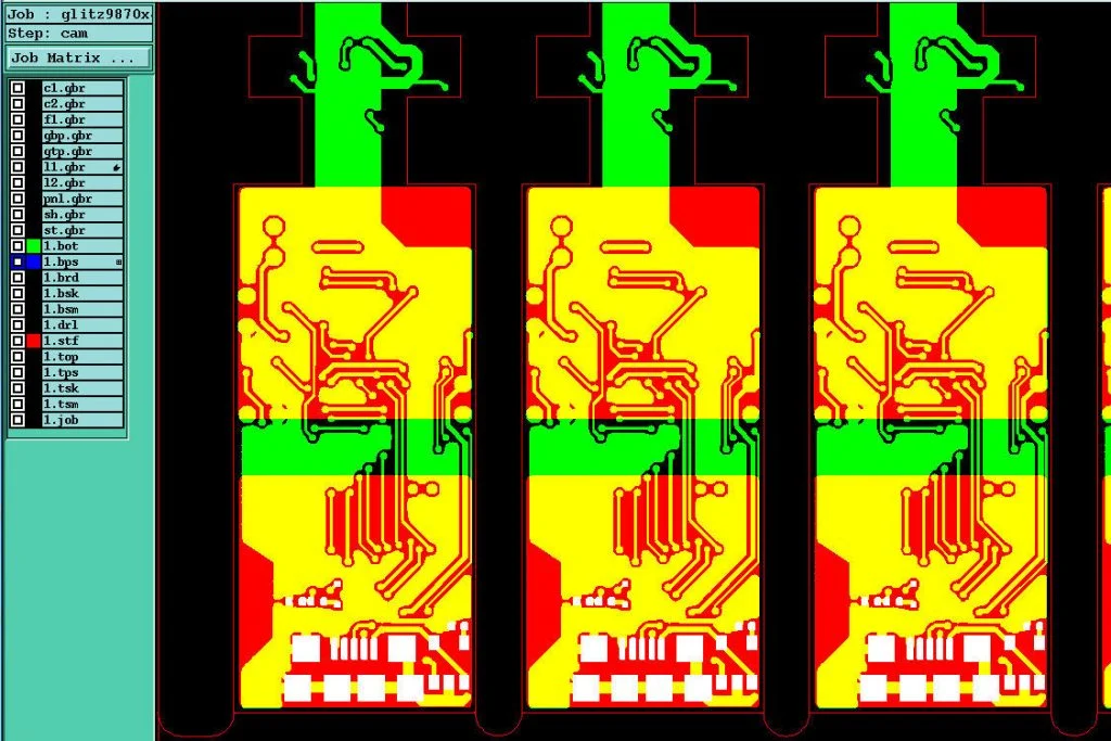
The picture 2 is the stiffeners (highlighted in yellow zone) designed by customer for SMD components which be assembled on opposite side of top layer, the design is close to be correct, but there are some SMD PADs on bottom side (back side), which would be covered by stiffeners so that would be an error if keep this design.
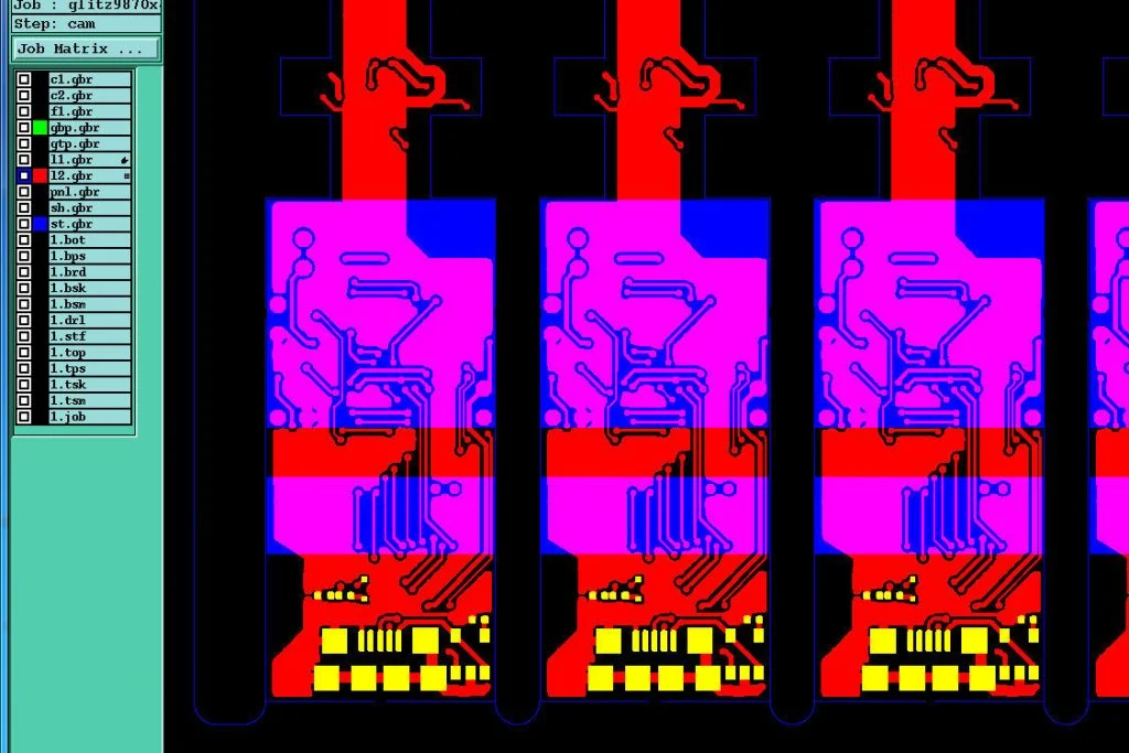
The picture 3 is the correct design after modification for stiffeners (highlighted in blue zone) which was canceled the bottom stiffeners on the zones where have SMD components (in the picture 2) placed. Now they are correct and can be released to flex PCB manufacturing process (picture 3).
For questions about how to design flex circuit stiffeners, you can freely contact us or send your inquiry to service@wellerpcb.com. Our technical engineer will have an answer to you quickly…