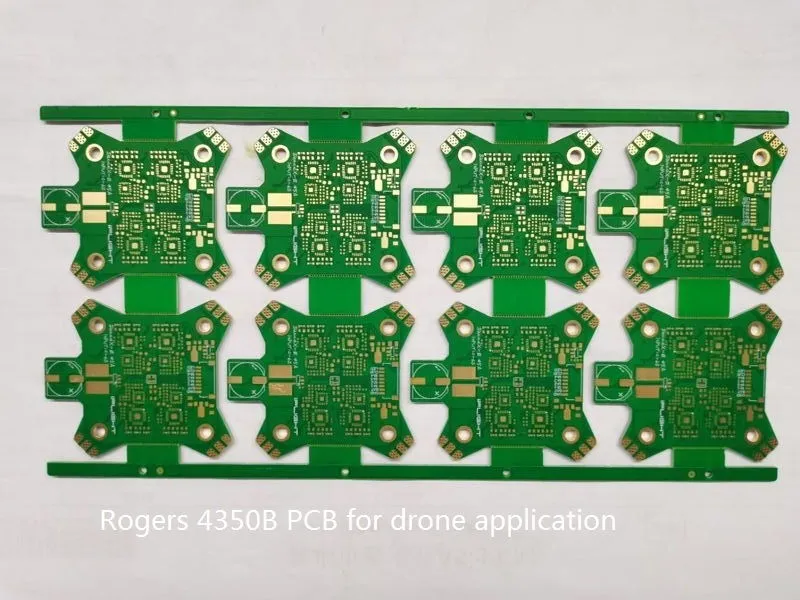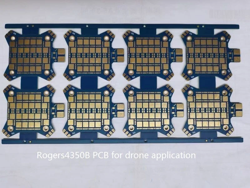
RF and Microwave Printed Circuit Boards
Radio frequency and microwave PCBs are a type of special circuit board designated to operate the RF or microwave signal. Therefore, these types of PCBs normally used in the application of high frequency signal transmission around megahertz to gigahertz frequency ranges. So, this type of PCB with its material is widely used in communication technologies such as mobile phones, military radars, drones, etc.


Highlighted Features and Benefits
Undoubtedly, compared to the traditional FR4 circuit boards, the raw material and manufacturing costs of high-frequency circuit boards are very high. However, based on some of its essential advantages and gains, it is still more and more applied to many electronic devices.
Common Issues and Solutions
Common Issues and It’s Solutions to RF PCB Design
| Item | Issues | Solutions |
| Power Planes | Usually, there are many problems such as parasitic effect and radiation loss because of the high frequency, which were discussed in the paper. Therefore, you would face serious problems of parasitic radiation. If you design the RF microwave circuits PCB by this way that power planes go around the edges of the board. | You can layout them between two ground planes. So that you may decouple the power supply layer and the power ground layer. |
| Ground loop rules | The minor wire loops, the less radiation and interference. It is very important that PCB designer need carefully to place the decoupling components on a RF circuit PCB. So that capacitive coupling will be eliminated.. | Therefore, PCB designer should optimize the current loops by putting the decoupling caps to the ground close to the pin. Hence, you must ensure that each pin or port has its own independent via hole’s path. |
| Thermal Relief | Another factors you must have to consider is the thermal stresses in the RF PCB design, too. Thus, the higher the frequency of the signal from an RF board, the more prominent the thermal stresses will occur. | However, you can avoid thermal stresses in a RF PCB by avoiding physical sharp changes in the trace width because it could negatively affect the radio frequency signal. So, you must avoid the right angle turns and instead of it by going for gradual and curved turns in the traces. Or, you can design it by another solution that to embed a copper coin (Embedded Copper coin and RFI Metal Backed PCB) near to some critical components or ICs that you need to have heat thermal transmission. |

Material Selection Reference
There are several types of RF material available for electronic designer to choose. However, which material should be selected mostly depends on the application of the electronic devices.
So, you can use the following chart to identify the suitable RF PCB material for your desired application.
The material list in below tables could provide general recommendation to PCB designer’s choice for their specific project.
| RF Application | RF Materials | Bonding Materials | Attributes & Characteristics |
| Consumer electronics | RO3006 RO3010 RO4835 | RO3000 Series Bondply 2929 Bondply | Cost effective with dependable electrical and thermal characteristics |
| Military/Space | RT/Duroid RO4000 | RO4450B/ RO4450F | The best in electrical and thermal performance and environmental durability |
| High power application | 6035HTC XT/Duroid | Superior thermal management | |
| Medical | RO4350B | RO4400 Bondply / 2929 Bondply | Versatile high performance properties to suit a range of device types |
| Automotive | RO3003 RO4000 RO4350B | RO4400 Bondply | Excellent electrical performance compatible with standard manufacturing processeses |
| Industrial | RO4835 RO4350B XT/Duroid | 2929 Bondply RO4400 Bondply | Excellent durability and environmental resistances, including oxidation |
Weller Technology is the top RF printed circuit board manufacturer in china as well as professional in producing microwave circuit board. We have dedicated R&D team and advanced production equipment to make sure the boards are fabricated to high quality standards and on-time.
Contact us freely if you are finding a capable of RF PCB manufacturer.


