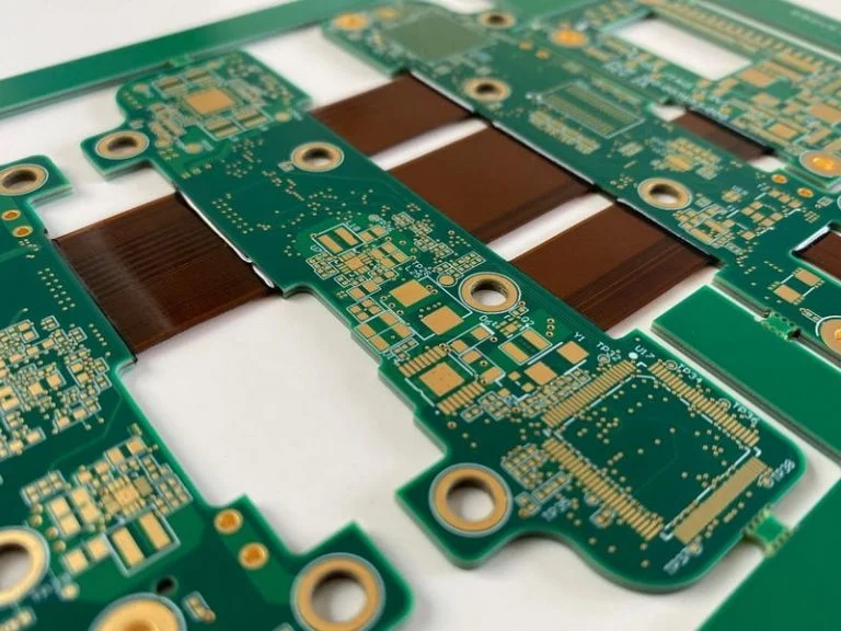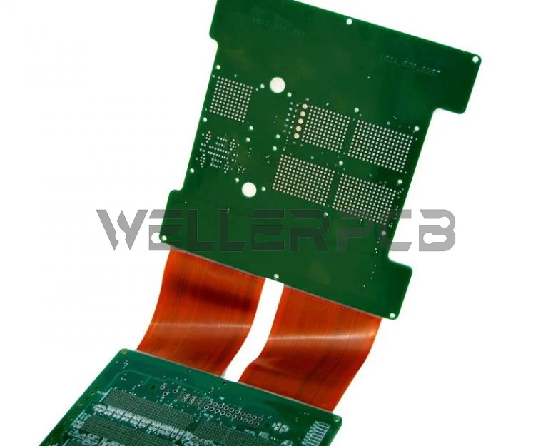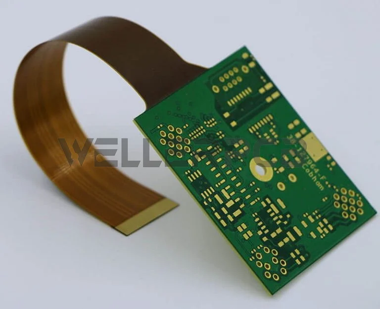
What is Rigid-flex PCB
Rigid-flex printed circuit boards is a complicated product that uses a blend of flexible and rigid board advances in an application. So when it comes to a new PCB design which demands a lot of interaction between our engineers and your technicians. Similar to other complex electronic products, early discussions between Weller and the designer is necessary to optimize the design for convenient in PCB fabrication process and to have the PCB manufacturing costs optimized. Here in Weller we can support advanced rigid-flex PCBs manufacturing and assembly for various applications in medical, IOT, defence, aerospace, and communication field.

Most of the rigid-flex flexible circuit boards comprised by different layers of flexible circuit substrates appended to at least one rigid laminate remotely and additionally inside, subject to the design of the application. The flexible laminate (substrates) are intended to be in a steady state of flex and are generally worked as the flexed bend during assembling or installation.
Designs for rigid-flex PCB fabrication are greater annoying as in contrast to the diagram of a frequent inflexible PCB board setting, as generally these sheets are designed in a 3D space, which additionally offers more outstanding spatial productivity. Frequent folding, rolling and twisting the flexible circuit board substrate to achieve its desired shape for the final application package by mapping the flexible rigid PCB is possible.

Advantages of Choosing Flex-Rigid PCB Board
While this sort of flexible circuit might be costly high compared classic rigid PCB board, it offers various significant benefits.
Also, the electronic device with rigid-flex PCB can perform well even in the worst conditions, especially those that are extremely warm. For example, the flex-rigid PCB have excellent performance even in the harshest situations, particularly those highlighting extraordinary warmth. Adhesiveless or adhesive based totally polyimide flex constructions, with cowl coat or bendy solder masks materials.

Rigid-Flex PCB vs. A Flexible Circuit
A rigid-flex PCB is a circuit board that the vast majority consider when they visualize a circuit board. These sheets interface electrical parts utilizing conductive tracks and different components, which are layout-ed on a non-conductive substrate. For flexible rigid PCB, most of the non-conductive substrate contains glass material, therefore, it enhance the hardness and strength of the circuit board. And, a rigid circuit board offers incredible support to the SMD components, just as fair thermal resistance.
Conductive circuit tracks of flexible PCB are included on a non-conductive laminate material, such circuit boards use a flexible substrate, such as polyimide (PI). The flexible base material enables flexible circuit board to dissipate heat, withstand vibration, and overlay up into different shapes. Due to their basic given features, flex PCB are progressively applied in innovative and compact hardware.

The Application of Rigid-fex PCB Manufacturing
Flexible rigid PCB has been used in a wide range of applications. They are commonly used in the small consumer items such as portable computers and mobile phones to avionics or modern military frameworks. The applications are listed below:
Rigid-flex PCB Applications in Medical Industry
Brain, heart, and respiratory monitoring system,handheld monitors, cochlear implants, imaging equipment.
Rigid-flex PCB Applications in Military Industry
Communication systems, Weapons guidance and control systems, GPS system, surveillance or tracking systems
Rigid-flex PCB Applications in Military Industry
Radar equipment, control tower systems, GPS, radio frequency communication systems, sensors integrity, motion sensors, noise and vibration testing systems, environmental monitor and climatic test chambers.
Rigid-flex PCB Applications in Telecommunication Industry
Communication base stations, communication satellites, signal processing integrity systems, wireless communication systems, routers and servers, transmission media, online signal expansion systems, etc
Materials Designing Tips for Rigid-flex PCB
During the rigid-flex PCBs configuration process, it is necessary to put some certain considerations to be considered for final item size varieties. In the assembling of rigid-flex printed circuit board, the flexible polyimide center will recoil once the fortified copper foil is scratched away. This variety must be verified in the design procedure.
Bending portion to be bent and the emphasis on the bending coverage may lead to the stress fracture is necessarily required.
Substrates
Conductive Material
Adhesives
Protective Coatings
Other than above materials, there are a few different optionally available base substances many times used in the manufacturing of rigid-flex PCB to beautify their operational reliability and excellence. These incorporate anti-tarnishing coatings, and support substrates. PCB manufactures choose these materials according to the client requirements, and precise application prerequisites.
The base material used for flex-rigid PCB extraordinarily decides the quality and the overall working performance of the rigid-flex sheets. As referenced before, PCB board base materials must be carefully selected after consulting a few criteria including some critical features such as shelf life, cost, and electrical prerequisites of the circuit, among others. This helps to produce rigid-flex circuit sheets that support years of trouble-free and reliable assistance.
Rigid-flex PCB Manufacturing Capability
| Item | Product | Technical Data |
|---|---|---|
| 01 | Layer Count | 2~16Layers |
| 02 | Min. Line Width/Space | 18um(finish Cu): 3.5/3.5mil 35um(finish Cu): 4.0/4.0mil |
| 03 | Min Space Between Coverlay Opening | 0.2mm |
| 04 | Edge of Coverlay Opening to Trace | 0.20mm(preferred) |
| 05 | Min Space between coverlay and solder pad | 0.15mm |
| 06 | Polyimide Films | 0.5 mil (12.5µ), 1 mil (25µ), 2 mils (50µ), 3 mils (75µ), 4mils(100µ), 5 mils(125µ) as custmer requested |
| 07 | Thermabond Adhesive | Acrylic/Modified Acrylic, Modified Epoxy, Polyimide |
| 08 | Copper Foils (RA or ED) | 1/4oz to 3oz |
| 09 | FR-4 in Multi-layer Flex Circuits | Laminated to flex circuit to create rigid flex boards, typically with vias |
| 10 | Stiffeners | Polyimide, Rigid FR4, PSA, metal, or customer requested |
| 11 | Solder Resist | Coverlay, LPI |
| 12 | Min. Finished Hole size | 0.20mm |
| 13 | Max. Finished Hole size | 6.30mm |
| 14 | Hole tolerance | ±0.05mm |
| 15 | Min.space between holes | 0.15mm |
| 16 | Minimum conductor edge to outline edge | ≥ 0.10mm |
| 17 | Tooling tolerance | Knife(Soft) tooling ± 0.25mm Steel(Hard) tooling ± 0.05mm CNC drill/rout ± 0.10mm |
| 18 | Maximum Layer to Layer Mis-registration | ± 0.10mm |
| 19 | Copper Plated Thickness (PTH only) | 8~15um;20~30um;30~70um(special) |
| 20 | PCB Surface Finish | Immersion Gold, HASL, Lead free HASL, Plating Hard Gold, OSP |
Weller Technology Offers You the Best Rigid-flex PCB Manufacturing Services
In case it comes to our flex and rigid-flex products, Weller offer a variety of cost effective solutions and capabilities that include single or double sided circuitry to higher technology multi-layer designs up to 16 layers. Beginning from selecting the best functional configuration, to choosing the proper connectors or components, Weller will help you meet or exceed all your applications requirements.
Our flex and rigid-flex PCBs are well manufactured for various applications in the medical, military, aerospace, and portable electronic devices industries.
Our skilled engineering team can assist you from beginning of design stages of your application all the way to end product production for all your flex and rigid-flex circuit needs.
In this way, we can freely offer customized items according to your product needs. Don’t hesitate to contact us for an estimate or any further questions.


