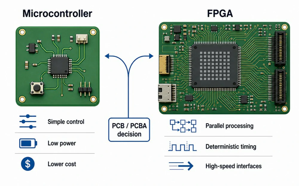
FPGA vs Microcontroller: Practical Answer
Simple Selection Rule
When Both Chips Make Sense
Some products use both. The MCU manages firmware, configuration, communication, startup, and system monitoring. The FPGA handles high-speed logic, parallel data paths, custom timing, or hardware acceleration.
| Product Need | Better Fit | Why | PCB/PCBA Note |
|---|---|---|---|
| Low-cost sensor device | Microcontroller | Integrated CPU, memory, and peripherals | Often simpler PCB and assembly |
| Battery-powered IoT node | Microcontroller | Strong low-power and sleep-mode support | Usually fewer support circuits |
| High-speed data capture | FPGA | Parallel logic and deterministic timing | May need multilayer PCB and impedance control |
| Video or image processing | FPGA | Handles many data streams at once | Routing, memory, and thermal design matter |
| Low-latency system control | FPGA or both | Fast parallel response | Plan signal integrity and test access early |
Difference Between FPGA and Microcontroller

Execution Model
| Factor | Microcontroller | FPGA | PCB Project Impact |
|---|---|---|---|
| Processing model | Sequential software | Parallel hardware logic | FPGA fits high-throughput or timing-critical tasks |
| Programming | Firmware, often C/C++ | HDL, such as Verilog or VHDL | FPGA development needs specialized validation |
| Latency | Can vary with interrupts and firmware load | Can be deterministic | Important for real-time systems |
| Power | Often lower for simple or idle tasks | Workload-dependent and often higher | Power rails and thermal planning may be harder |
| Cost | Usually lower chip and board cost | Often higher device and PCB cost | Total cost includes PCB layers, assembly, and testing |
When to Choose a Microcontroller
Good MCU Applications
- IoT sensors and smart home devices
- Wearable and battery-powered products
- Basic industrial control boards
- Simple motor control systems
- Consumer electronics with moderate processing needs
PCB Advantages of MCU Designs
MCUs can reduce PCB complexity. Many MCU designs use common packages, fewer power rails, lower routing density, and standard SMT assembly. This can lower prototype risk and production cost.

When to Choose an FPGA
Good FPGA Applications
- High-speed data acquisition boards
- Image and video processing systems
- Telecommunications and networking equipment
- Multi-channel sensor processing
- Low-latency industrial or robotics control
Design Trade-Offs
PCB Design Considerations for FPGA vs MCU

Key PCB Design Checks
- Package type, pitch, pin count, and escape routing
- Power rails, sequencing, and decoupling placement
- Clock, reset, and configuration routing
- DDR, LVDS, PCIe, USB, Ethernet, or SERDES requirements
- Controlled impedance, return paths, and reference planes
- Thermal paths, copper area, airflow, programming, and test access
Stackup and Signal Integrity
| PCB Design Factor | MCU-Based Board | FPGA-Based Board |
|---|---|---|
| Layer count | Often lower | Often higher for dense or high-speed designs |
| Routing density | Usually moderate | Can be high due to pin count and interfaces |
| Package risk | QFN, QFP, or BGA depending on MCU | BGA is common for larger FPGAs |
| Power design | Often simpler | Multiple rails and stricter decoupling are common |
| Signal integrity | Depends on interfaces | Often more critical |
| Thermal design | Usually simpler | May need thermal vias, copper pours, or airflow |
PCB Manufacturing, Assembly, and Testing Impact

An FPGA board may add manufacturing constraints. Fine-pitch BGA packages can require tighter routing, smaller vias, via-in-pad, microvias, or HDI PCB manufacturing. High-speed designs may also need controlled impedance and stackup review.
Inspection and Test Planning
Files and Requirements to Prepare
- Gerber files and drill files
- BOM with approved manufacturer part numbers
- Pick and Place file and assembly drawing
- PCB stackup and controlled impedance requirements
- Surface finish requirement
- Programming or firmware instructions
- Functional test procedure and special inspection notes
A DFM check helps catch fabrication risks, while a DFA check helps catch assembly risks. WellerPCB also publishes practical notes on common PCB DFM mistakes that can delay fabrication or assembly.
Cost, Lead Time, and Sourcing Considerations

Cost Drivers
Lead Time and Supply Risk
Manufacturing Review Checklist Before Production
Production Readiness Checks
- Confirm package pitch, footprint, and escape routing.
- Check whether the board needs multilayer, HDI, via-in-pad, or controlled impedance.
- Review power rails, sequencing, decoupling, and thermal paths.
- Confirm the surface finish for fine-pitch or BGA components.
- Define AOI, X-ray, ICT, flying probe, or functional testing needs.
- Prepare Gerber, drill, BOM, Pick and Place, assembly drawing, and test notes.
- Run DFM and DFA checks before pilot or production builds.
If you are preparing a board for production, share Gerber files, BOM, Pick and Place data, stackup needs, controlled impedance notes, and test requirements through the WellerPCB contact page for a practical fabrication and assembly review.

Common Mistakes When Choosing FPGA or Microcontroller
The wrong chip choice often comes from judging only performance or unit price. For production boards, compare workload, PCB complexity, assembly risk, testing needs, and long-term sourcing.
Mistakes to Avoid
- Choosing an FPGA only because it sounds faster. If the task is simple control, an FPGA may add cost and complexity without improving the product.
- Forcing a microcontroller into a workload that needs parallel processing or strict timing. Overloaded firmware can make the design fragile.
- Ignoring PCB complexity. A high-pin-count FPGA can turn a simple board into a dense multilayer design.
- Skipping power and thermal checks. FPGA rails, current demand, and decoupling should be reviewed before routing.
- Treating prototype success as production readiness. A working prototype may still be hard to assemble, inspect, test, or source at scale.