Introduction
As a first thought, one might think that the 0 Ohm resistor is unnecessary; after all, why would someone use a resistor with no resistance? This is one of the most common questions among students, beginner designers, and hobbyists. Interestingly, a 0-ohm resistor is one of the most practical components used in electronic and PCB design. It helps engineers simplify their PCB designs, troubleshoot hardware after manufacturing, and create configurable hardware designs.
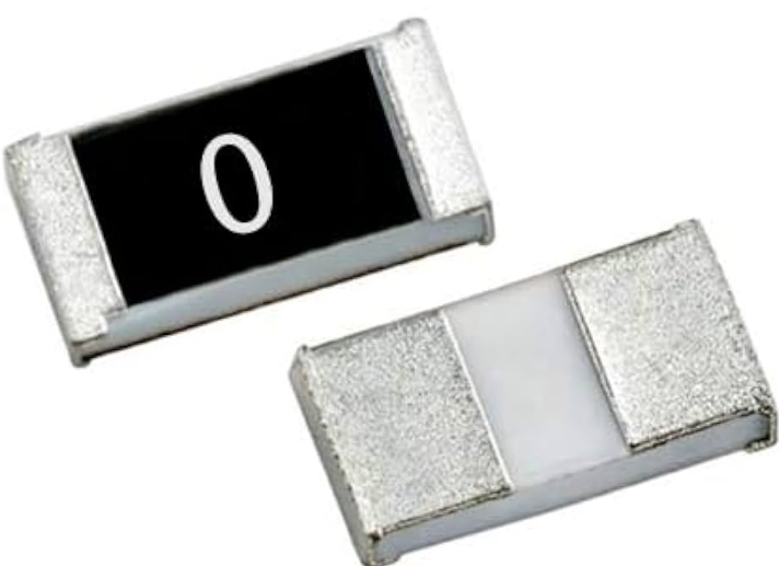
People often mix up the wire jumper with a 0-ohm resistor. However, 0 ohm resistors are standard SMT components that can be placed automatically during PCB assembly. The addition of zero ohm resistors in PCB designs gives engineers the flexibility to modify circuits, isolate circuit blocks, and separate the digital and analog Grounds.
This technical tutorial guide will cover how zero ohm resistors work, why they are widely used in PCB designs, package types, practical applications, and mistakes to avoid.
What Is a 0 Ohm Resistor?
A zero ohm resistor, also known as a zero-ohm resistor, 0R resistor, or resistor jumper, is an electronic component that provides a zero-resistance path. Unlike other resistors, the primary purpose of a 0-ohm resistor is not to limit current. Its primary purpose is to act as a conductive bridge between two electronic circuits.
A resistor with zero resistance may often lead to unnecessary. However, zero-ohm resistors solve several practical challenges in PCB design and manufacturing. They allow engineers to isolate the two circuit sections during debugging and create configurable hardware designs with ease and convenience. These advantages make the o ohm resistor a widely used component in modern electronics, from consumer electronics to IoT devices, smart wearable devices, and so on.
| 📱 Smartphones | 💻 Laptops |
| ⌚ Wearable Devices | 🌐 Networking Equipment |
| 🚗 Automotive ECUs | 🏭 Industrial Controllers |
| 🏥 Medical Devices | 🔧 Embedded Systems |
Why Not Just Use a Wire?
One of the interesting questions asked by many beginners is, “If a 0 ohm resistor behaves like a short circuit, why not simply use a wire?” The question may be technically valid, but using a simple wire has manufacturing and several design issues that make a 0 ohm resistor a preferred choice.
From a conceptual point of view, a wire jumper and zero ohm resistors provide a low-resistance connection between two points in circuit design. However, a simple wire jumper cannot be placed by a pick-and-place machine during the SMT assembly process. Whereas a 0-ohm resistor can be automatically placed by a pick-and-place machine. Therefore, eliminating the manual soldering and manufacturing costs. This is where the 0-ohm resistor won the game over a wire jumper.
Table. Comparison between a 0 Ohm resistor and a wire jumper in PCB design.
Construction and Working Principle
A 0-ohm resistor is a specially designed electronic component to provide a low-resistance electrical connection between two electronic circuits. It looks exactly like the other SMT components; therefore, automatically picked up by a PCB assembly machine known as a pick-and-place machine.
0 Ohm Resistor Construction
Unlike conventional resistors, which use a resistive film to limit current, a 0 Ohm resistor contains a highly conductive metal element that directly connects its two terminals. The conductive path is made up of copper or nickel. Therefore, acting as a short circuit while also maintaining mechanical stability. These resistors also come in various packages such as 0201, 0402, 0603, 0805, and 1206, depending on the designer’s requirements.
How Does a 0 Ohm Resistor Works?
The working principle of a zero-ohm resistor is straightforward. When current flows through the component, it travels directly through the internal conductive element from one terminal to the other with minimal voltage drop. Since the resistance is extremely low, the resistor behaves almost like a direct PCB trace or wire connection.
Features of 0 Ohm Resistor
Another interesting feature of a zero-ohm resistor is that engineers often intentionally leave a connection optional. Therefore, during assembly, the resistor can either be populated to complete the circuit or omitted to disconnect that portion of the circuit. This approach is widely used for selecting power sources, enabling or disabling features, and separating analog and digital grounds in PCB design layout.
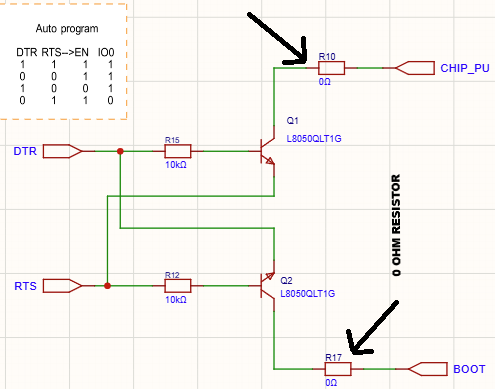
Electrical Characteristics
Although a 0 Ohm resistor is designed to function as a conductive link, it still possesses measurable electrical characteristics that should be considered during PCB design. Like any physical electronic component, it exhibits a small amount of resistance, current-carrying capability, power rating, parasitic inductance, and parasitic capacitance. Understanding these characteristics helps PCB designers select the appropriate package size and avoid reliability issues in high-current or high-speed applications.
Unlike an ideal short circuit, a real zero ohm resistor does not have exactly 0 Ω resistance. Depending on the manufacturer and package size, its resistance typically ranges from a few milliohms (mΩ) to several tens of milliohms. For most digital and general-purpose circuits, this small resistance has virtually no effect. However, in precision analog circuits or applications carrying high current, the resulting voltage drop and power dissipation should be taken into account.
Table. Typical electrical characteristics of a 0 Ohm resistor and their PCB design considerations.
Types of 0 Ohm Resistors
All zero ohm resistors perform the same basic function of creating a low-resistance electrical connection; they are available in several types to suit different PCB design, manufacturing, and assembly requirements. The selection depends on factors such as mounting technology, current-carrying capability, package size, and application. Some of the widely used zero-ohm resistor types are explained in this section below.
| 🔹 Surface Mount (SMD) 0 Ohm Resistors | 🔹 Through-Hole 0 Ohm Resistors |
| 🔹 Thick Film 0 Ohm Resistors | 🔹 Precision Low-Resistance Jumpers |
Surface Mount (SMD) 0 Ohm Resistors
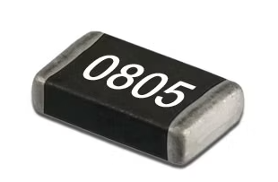
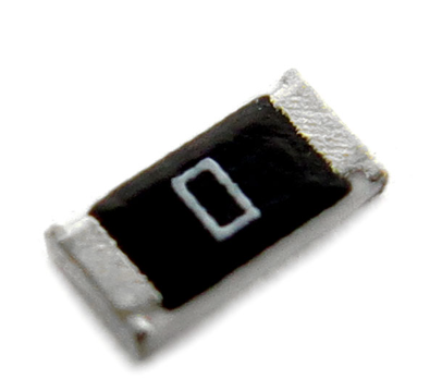
Surface Mount Device (SMD) 0 Ohm resistors are the most widely used type in modern electronics. They are designed for automated SMT assembly, making them ideal for high-volume PCB manufacturing.
Through-Hole 0 Ohm Resistors
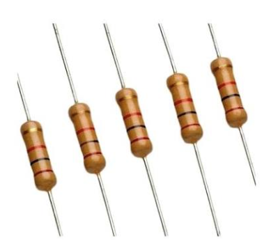
Through-hole zero ohm resistors have the appearance of conventional axial resistors but contain a conductive element instead of a resistive material. They are inserted through drilled PCB holes and soldered on the opposite side.
Thick Film 0 Ohm Resistors
Most commercially available SMD zero ohm resistors are manufactured using thick film technology. They offer low cost, good mechanical strength, and compatibility with standard SMT manufacturing processes.
Precision Low-Resistance Jumpers
Some manufacturers produce 0 Ohm resistors specifically designed for carrying higher currents. These components use wider conductive elements and larger package sizes to reduce resistance and improve heat dissipation.
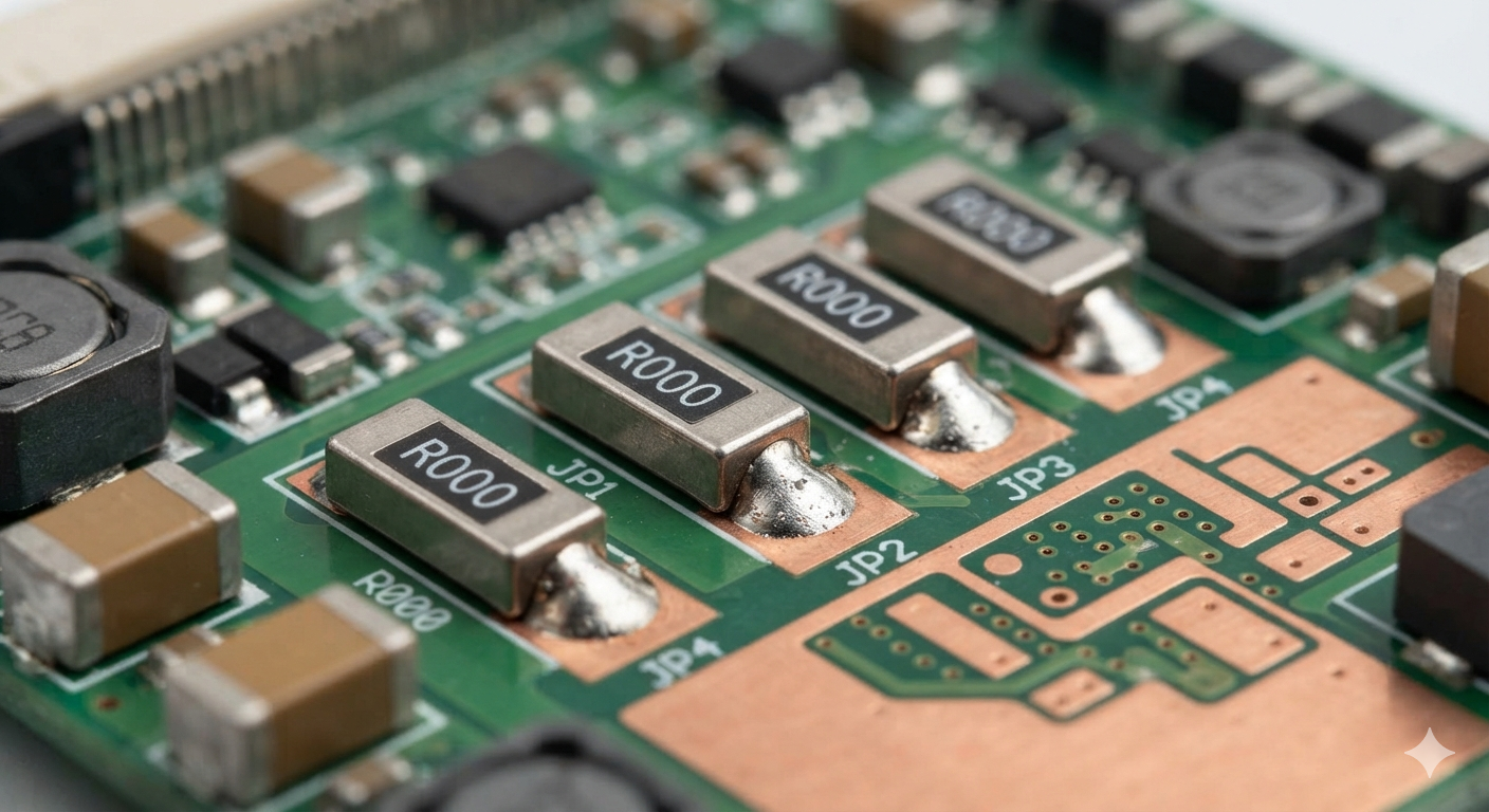
Table. Comparison of different types of 0 Ohm resistors based on mounting method, applications, and advantages.
Hardware Design Requirements
0 Ohm resistor is one of the simplest components used in PCB design. However, selecting and placing it correctly is essential for ensuring reliable circuit operation, efficient PCB manufacturing, and easy future modifications. Before adding a 0 Ohm resistor to your schematic or PCB layout, several hardware design considerations should be taken into account.
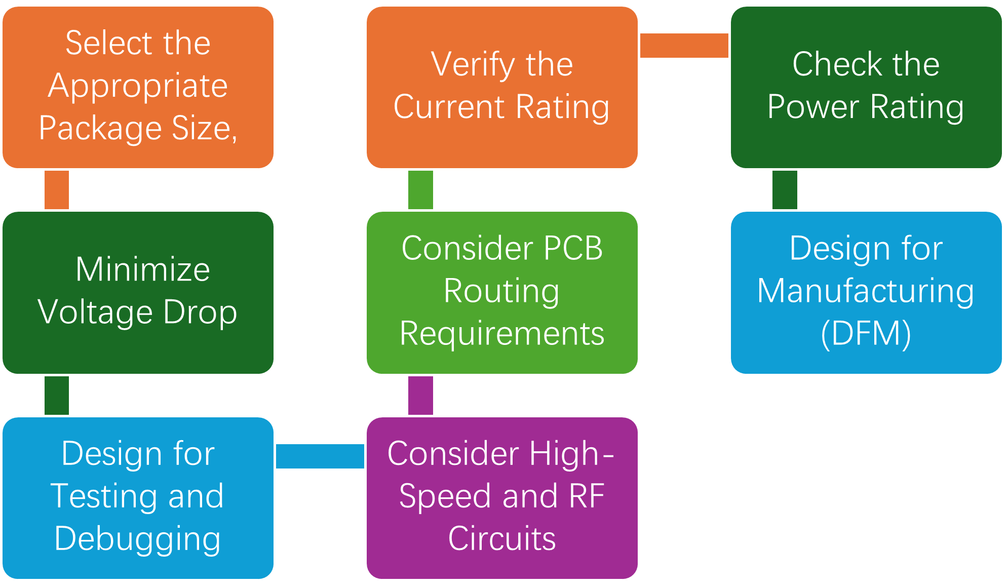
Select the Appropriate Package Size
Choose the package size based on the available PCB space, manufacturing capabilities, and expected current flow. Smaller packages save board space, while larger packages can carry higher currents and dissipate heat more effectively.
Verify the Current Rating
Not all 0 Ohm resistors can carry the same amount of current. The maximum continuous current depends on the package size, internal conductor, and manufacturer.
The table below summarizes the typical 0 ohm resistor packages along with their current ratings.
Table. Typical current ratings of common SMD 0 Ohm resistor package sizes.
Therefore, it is recommended to verify the current rating as per your project specifications. This become essential in power supply lines, battery connections, and motor driver circuits.
Check Power Rating
It is now obvious that the voltage drop across a 0 Ohm resistor is very small; excessive current can still generate heat. Select a component with an adequate power rating to prevent overheating and long-term reliability issues. Therefore, for high-current applications, use a larger package instead of relying on a small SMD resistor.
Minimize Voltage Drop
Every conductive path introduces a small voltage drop, even a 0 ohm resistor. Therefore, when designing precision analog circuits or battery-powered devices, keep the current path as short as possible and choose a resistor with a low specified resistance.
Consider PCB Routing Requirements
One of the main reasons for using a zero ohm resistor is to simplify PCB routing. It can act as a jumper to cross signal traces on a single-layer or double-layer PCB without requiring additional PCB layers. Common examples include optional circuit connections, selecting different signal paths, and configuring multiple PCB variants.
Design for Manufacturing (DFM)
To ensure smooth manufacturing, always use standard package sizes of zero-ohm resistors, always maintain pad dimensions recommended by the footprint library, ensure enough spacing with adjacent components.
Design for Testing and Debugging
Many design engineers intentionally place zero-ohm resistors for later PCB testing and debugging. For example, a zero-ohm resistor on the power rail helps you activate or deactivate the power line by just placing and removing the zero-ohm resistor.
High-Speed and RF Circuits
In most high-speed designs such as RF designs and sensitive analog circuits, a zero-ohm, resistor introduces parasitic inductance and capacitance. Therefore, in such designs keep the traces as short as possible, avoid unnecessary series zero ohm resistors in critical signal paths, and evaluate signal integrity issues before using zero ogm resistors.
Applications of 0 Ohm Resistors
Zero-ohm resistors are a simple conductive link, but it serves many critical functions in modern electronics. PCB designers use them in product development, schematic designs for testing, debugging, future upgrades, and so on.
🔀 PCB Trace JumpingAllows signal traces to cross on single- and double-layer PCBs without adding extra board layers or wire jumpers. |
⚙️ Hardware ConfigurationEnables multiple hardware configurations by simply installing or omitting the resistor during PCB assembly. |
🛠 Prototype Development & DebuggingActs as a removable jumper for testing, current measurements, fault isolation, and hardware debugging. |
🧪 Production TestingSimplifies factory testing, programming, and verification of individual circuit sections during manufacturing. |
🌍 Ground SeparationProvides a controlled connection between analog and digital grounds to reduce electrical noise. |
⚡ Power DistributionRoutes power between PCB sections while allowing easy isolation for testing and future upgrades. |
📶 EMC & EMI OptimizationCan be replaced with a ferrite bead or resistor during EMC testing to improve noise suppression. |
🤖 Automated PCB AssemblySupports fully automated SMT assembly, reducing manufacturing cost while improving production consistency. |
Can a 0 Ohm Resistor Replace a Wire?
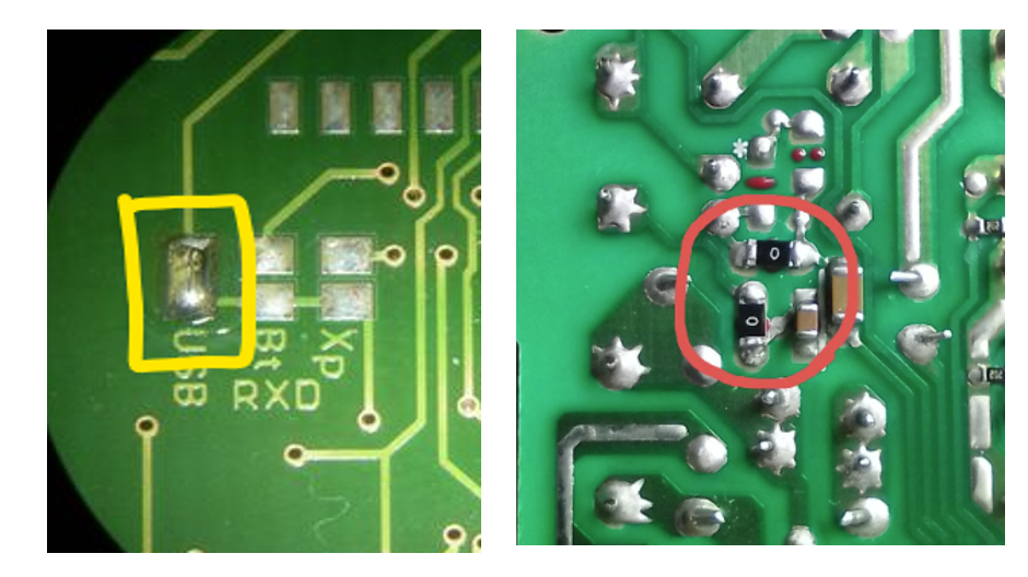
Yes, a zero-ohm resistor can replace a wire in most applications, but the two cannot be interchanged. Both have low-resistance connection points between two points, but a zero-ohm resistor comes with advantages that a simple wire lacks.
A zero-ohm resistor also provides greater design flexibility. Engineers can easily install or remove it to change circuit configurations. However, there are situations where a wire is the better choice. If the connection must carry very high current, withstand mechanical stress, or span a long distance on the PCB, a copper wire or a dedicated PCB trace may provide lower resistance and better reliability.
Can a 0 Ohm Resistor Be Used as a Fuse?
A common misconception is that a zero-ohm resistor can function as a fuse because it may burn open when high current flows through it. Therefore, this is not recommended. Unlike a fuse, a zero-ohm resistor is not designed to provide overcurrent protection. Its failure current depends on factors such as the manufacturer, package size, ambient temperature, PCB layout, and duration of the overload. As a result, it cannot guarantee safe or repeatable circuit protection.
Zero Ohm Resistor vs Wire Jumper vs Ferrite Bead
A 0 Ohm resistor, wire jumper, and ferrite bead may look similar in a PCB design because they are all placed in series with a circuit trace. However, they serve completely different purposes. Choosing the wrong component can affect signal integrity, electromagnetic compatibility (EMC), manufacturability, and overall circuit performance. The core differences between these three distinct yet confusing components are listed in the table below. This will help designers to choose the right one for their design applications.
Table. Comparison of 0 Ohm resistors, wire jumpers, and ferrite beads in PCB design.
Conclusion
To sum up, a zero-ohm resistor is much more than a simple conductive link—it is a versatile component that improves PCB routing, simplifies automated SMT assembly, supports hardware configuration, and makes testing and debugging more efficient. Although it provides an almost zero-resistance connection, its value lies in the flexibility and manufacturability it brings to modern PCB designs.
Frequently Asked Questions (FAQ)
A 0 Ohm resistor provides the same electrical connection as a wire while being compatible with automated SMT assembly.
Yes, but it depends on the resistor’s package size and current rating. Larger packages such as 1206 or 2512 can handle higher currents than smaller packages like 0402 or 0201
Yes, in many low-current circuits, a wire can provide the same electrical connection. However, a 0 Ohm resistor is generally preferred because it supports automated PCB assembly.
No. A Zero Ohm resistor is not designed to provide overcurrent protection.
Common SMD package sizes include 0201, 0402, 0603, 0805, 1206, and 1210.
A 0 Ohm resistor acts as a conductive jumper with very low resistance, while a ferrite bead is used to suppress high-frequency noise
Use a 0 Ohm resistor when you need a simple electrical connection, PCB routing flexibility, or hardware configuration. Use a ferrite bead when your goal is to reduce high-frequency noise, improve EMI performance, or filter power supply lines.