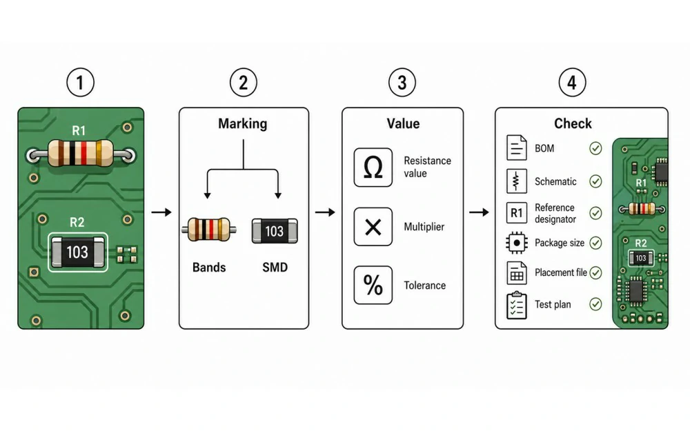
What Resistor Markings Tell You
Most resistor markings identify the nominal value and tolerance. Some also show temperature behavior. In PCBA work, these details are useful, but they do not replace document control. A part can look correct and still have the wrong package, power rating, tolerance, or approved manufacturer part number.

| Item | What It Means | Why It Matters |
|---|---|---|
| Resistance value | Nominal value in Ω, kΩ, or MΩ | Controls current, voltage division, feedback, sensing, and pull-up strength |
| Multiplier | Scale applied to the marked digits | Prevents errors such as 100Ω vs 10kΩ |
| Tolerance | Allowed variation, such as ±1% or ±5% | Affects precision, calibration, and substitutions |
| Temperature coefficient | Resistance change with temperature, usually ppm/°C | Matters in precision, industrial, and high-reliability circuits |
| Package and power rating | Physical size and safe power dissipation | Affects footprint fit, heat, soldering, and long-term reliability |
Quick PCB Resistor Check Process
- Identify the type. Check whether the resistor is through-hole, SMD, zero-ohm, low-ohm, precision, or unmarked.
- Read the visible code. Use color bands, numeric SMD codes, R notation, or EIA-96 where applicable.
- Compare with the BOM. Confirm value, tolerance, package, power rating, reference designator, and manufacturer part number.
- Check the circuit role. Dividers, feedback loops, current sense paths, and termination networks are sensitive to wrong values.
- Confirm placement data. Make sure the package in the BOM matches the PCB footprint and Pick and Place file.
- Measure with context. In-circuit readings can be affected by parallel paths, so check the schematic before judging a resistor as wrong.
How to Read Through-Hole Resistor Color Codes

Find the First Band
Start from the side where the value bands are grouped. Gold or silver is usually the tolerance band, so it normally sits on the right. If the direction is unclear, compare the possible values with the BOM or schematic.
4-Band Resistors
A 4-band resistor uses two value digits, one multiplier, and one tolerance band. Brown, black, red, gold means 10 × 100 = 1,000Ω, or 1kΩ, with ±5% tolerance.
5-Band and 6-Band Resistors

Tolerance Range
Resistor Color Code Table
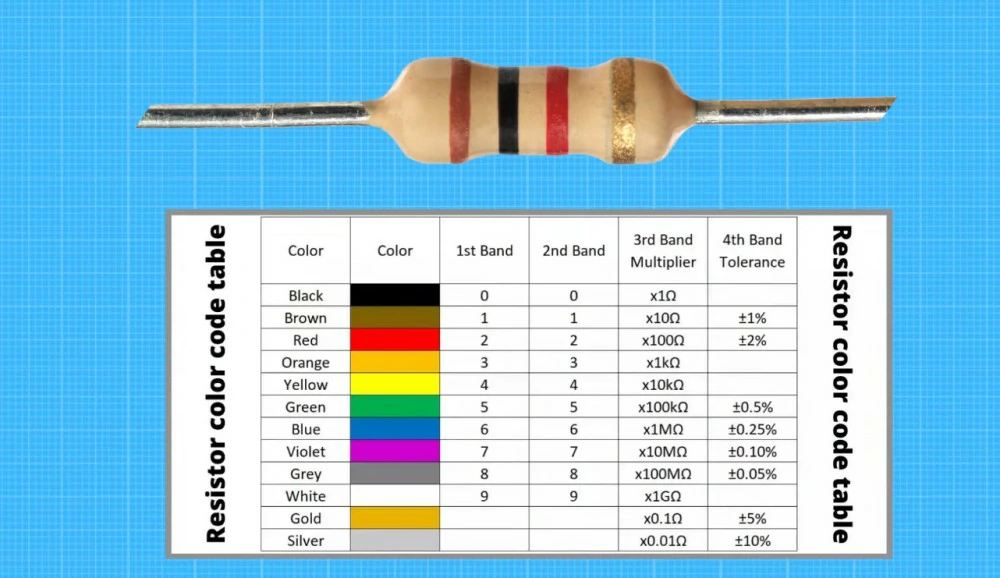
| Color | Digit | Multiplier | Tolerance | Temp. Coefficient |
|---|---|---|---|---|
| Black | 0 | ×1 | Not common | 250 ppm/°C |
| Brown | 1 | ×10 | ±1% | 100 ppm/°C |
| Red | 2 | ×100 | ±2% | 50 ppm/°C |
| Orange | 3 | ×1k | Not common | 15 ppm/°C |
| Yellow | 4 | ×10k | Not common | 25 ppm/°C |
| Green | 5 | ×100k | ±0.5% | 20 ppm/°C |
| Blue | 6 | ×1M | ±0.25% | 10 ppm/°C |
| Violet | 7 | ×10M | ±0.1% | 5 ppm/°C |
| Gray | 8 | ×100M | ±0.05% | 1 ppm/°C |
| White | 9 | ×1G | Not common | Not common |
| Gold | Not used | ×0.1 | ±5% | Not common |
| Silver | Not used | ×0.01 | ±10% | Not common |
| None | Not used | Not used | ±20% | Not used |
How to Read SMD Resistor Codes

3-Digit and 4-Digit Codes
| Marking | How to Read It | Value |
|---|---|---|
| 103 | 10 × 103 | 10kΩ |
| 472 | 47 × 102 | 4.7kΩ |
| 1001 | 100 × 101 | 1kΩ |
| 4992 | 499 × 102 | 49.9kΩ |
| 000 | Zero-ohm jumper | Approximately 0Ω |
R Notation and Low-Ohm Parts
EIA-96 and Unmarked Parts
Through-Hole vs SMD Resistor Identification
| Item | Through-Hole Resistor | SMD Resistor |
|---|---|---|
| Common marking | Color bands | Numeric code, letter code, or no marking |
| Assembly method | Hand soldering, wave soldering, or through-hole assembly | SMT assembly and reflow soldering |
| Visual risk | Reading bands backward or confusing colors | Misreading small codes or assuming unmarked parts are wrong |
| Best check | Marking, BOM, schematic, and measurement | BOM, placement file, assembly drawing, inspection, and testing |
PCB Design and Assembly Checks
Reading a resistor tells you what the part appears to be. However, it does not prove that the assembled board matches the design. Before production, check the design files, sourcing data, and assembly requirements together.
Match the BOM and Schematic
Confirm Footprint and Package Size
Control Substitutions
Use Clear Reference Designators
Silkscreen usually shows R1, R2, and R3 rather than resistor values. Clear labels help technicians locate parts during inspection, rework, and failure analysis. Good PCB silkscreen design reduces confusion during manual checks.

Common Mistakes
Reading in the Wrong Direction
Confusing Similar Markings
Ignoring Ratings
Measuring In-Circuit Too Quickly
Inspection and Testing
- Manual inspection can confirm markings, placement, solder joints, and obvious value errors.
- AOI inspection for PCB assembly can check presence, position, visible markings, and solder quality, but it may not prove every resistor value.
- Flying probe testing can support prototype or low-volume validation when a fixture is not practical.
- In-circuit testing can support production checks when the board has suitable test access.
- Functional testing confirms board-level behavior and can catch critical wrong-value resistor issues.