Table of Contents

IPC J-STD-001 for PCB Assembly and Supplier Control

IPC J-STD-001 requirements for controlled PCB assembly quality and workmanship
IPC J-STD-001 defines material, process, inspection, and acceptance requirements for soldered electrical and electronic assemblies. It helps OEMs, EMS providers, engineers, and quality teams specify how a PCBA will be built and verified.
Writing only “IPC compliant” on an assembly drawing is not enough. A usable manufacturing specification must identify the revision, product class, applicable addendum, inspection coverage, testing, traceability, and customer-specific requirements.

What IPC J-STD-001 Controls

IPC J-STD-001 covers more than finished-joint appearance. It also addresses production methods, personnel, process controls, verification, and records.

Processes Within Its Scope

IPC J-STD-001 scope covering SMT, through-hole assembly, soldering, cleaning, inspection, and rework
  • SMT, through-hole, and mixed-technology assembly
  • Hand, reflow, wave, and selective soldering
  • Solder alloys, solder paste, flux, adhesives, and cleaning materials
  • Component and printed-board solderability
  • Visible and selected hidden solder connections
  • Cleaning, conformal coating, staking, and encapsulation
  • Requirements governing rework, repair authorization, reinspection, and acceptance; detailed procedures may reference IPC-7711/7721
IPC released Revision J in 2024. Check the official IPC document revision table because older drawings may specify Revision H or earlier. Resolve the required revision before quotation or production.

What the Standard Does Not Replace

The standard does not replace PCB design, bare-board fabrication, or complete product validation. Separate engineering controls are still needed for:
  • Layer stack-up, controlled impedance, trace width, spacing, and via design
  • Laminate selection, copper weight, drill limits, and fabrication tolerances
  • Bare-board performance and acceptance requirements
  • Component datasheets and approved substitution rules
  • ICT, flying-probe, firmware, and functional testing
  • Environmental, safety, and regulatory qualification
A PCBA can pass workmanship inspection and still fail because of an incorrect component, open circuit, firmware issue, thermal weakness, or application-level design error.

IPC J-STD-001 vs IPC-A-610

The two standards support different parts of the same manufacturing workflow. IPC states that J-STD-001J and IPC-A-610J are often used together for electronic assembly production and acceptance.
Comparison Point IPC J-STD-001 IPC-A-610
Primary purpose Defines material, process, and acceptance requirements for soldered electrical and electronic assemblies Provides visual acceptability criteria for completed electronic assemblies
Typical users Process engineers, assemblers, and quality teams Inspectors, operators, customers, and quality teams
Main production stage Planning and manufacturing Inspection and acceptance
Process evidence Major focus Not the primary focus
Electrical function Not proven Not proven
For a wider comparison of bare-board and assembly documents, review the roles of IPC fabrication and assembly acceptance standards.

Compliance Is Not the Same as Personnel Certification

An individual IPC credential may support operator or inspector proficiency. It does not prove that every production line, material, process, or completed assembly meets the customer’s requirements.

IPC also operates a separate Qualified Manufacturers List validation program, illustrating that personnel training and company-level process validation are different claims.

How to Specify Revision, Class, and Documentation

A clear specification prevents disputes about requirements, substitutions, and production evidence.

Selecting Class 1, Class 2, or Class 3

IPC Class 1, Class 2, and Class 3 selection based on failure impact, environment, and service continuity
The customer or product owner should select the class. The choice should reflect the required service continuity, operating environment, product life, and consequence of failure.
  • Can temporary failure be tolerated?
  • Will the product face heat, vibration, moisture, or contamination?
  • Could failure affect safety, mission performance, or critical operations?
  • Are added traceability, inspection, or documentation controls required?
  • Does a contract or sector-specific requirement define the class?
Do not select Class 3 merely because it sounds more reliable. It can add qualification, inspection, documentation, and approval work; product sector alone does not determine the class.
Additional context is available in this comparison of IPC Class 2 and Class 3 requirements.

Required Manufacturing Data

A practical PCB assembly package should include:
  1. A BOM with manufacturer part numbers and approved alternatives
  2. Gerber files or intelligent manufacturing data
  3. A pick-and-place or centroid file
  4. Assembly drawings with polarity and orientation details
  5. The required standard, revision, class, and addendum
  6. Inspection, electrical test, and functional test requirements
  7. Traceability and record-retention expectations
  8. Rules for substitutions, deviations, rework, and repair
Specification Warning

Common Specification Failure

A drawing that specifies Class 3 but omits the applicable revision cannot be quoted unambiguously when the purchase order says only “IPC compliant.” Resolve the conflict in writing during DFM and manufacturing planning.

Specification Example

Copyable Procurement Specification

Adapt the bracketed field and project-specific controls before use.

Assemblies shall comply with IPC J-STD-001J, Class 2. Acceptance shall be evaluated to IPC-A-610J, Class 2. Applicable addenda: [specify]. X-ray coverage, functional testing, traceability, rework approval, and record-retention requirements shall be defined in the purchase documentation.

Confirm the required revision, class, addenda, and customer-specific controls before issuing the RFQ or purchase order.

PCB Fabrication and Assembly Process Controls

Assembly quality depends on the interaction between the bare PCB, component finishes, soldering materials, thermal process, and inspection plan. Final inspection cannot correct an unstable or incompatible process.

Soldering Materials and Solderability

Material controls may reference J-STD-004 for fluxes, J-STD-005 for solder paste, and J-STD-006 for electronic-grade solder alloys. J-STD-002 addresses component termination solderability, while J-STD-003 addresses printed-board solderability.

The assembler should verify material identity, shelf life, storage, moisture handling, datasheet limits, and substitution approval. The soldering system must also suit the selected PCB surface finish.
ENIG, HASL, OSP, ENEPIG, and other finishes have different storage, flatness, solderability, and cost considerations. J-STD-001 does not require one universal surface finish.

SMT and Through-Hole Manufacturability

Hand soldering and rework of surface-mount IC leads on a PCB
SMT controls can include stencil design, solder paste inspection, placement accuracy, polarity verification, moisture-sensitive component handling, reflow profiling, and post-reflow inspection. Dense BGA and bottom-termination packages require inspection planning before layout release.
Through-hole assembly requires control of component seating, lead preparation, board support, soldering method, thermal conditions, and inspection access. Mixed-technology boards may pass through reflow, selective soldering, wave soldering, hand soldering, and later rework.
Related layout risks are covered in these SMT assembly design guidelines.

DFM, Thermal Mass, and Fabrication Risk

Heavy copper, large ground planes, metal-backed areas, and thick multilayer stack-ups can increase thermal mass. This may affect paste selection, profiling, selective soldering, and hand-rework difficulty.
DFM and DFA checks should review footprints, solder mask openings, polarity, via-in-pad construction, spacing, rework access, panel support, and test points. A formal PCB assembly DFM review should identify risks before file release.

Cleaning and Process Changes

“No-clean” does not mean residues can be ignored under every process or service condition. Low-standoff packages, local rework, humidity, high voltage, and harsh environments may justify additional residue evaluation.
A change to solder paste, flux, cleaning chemistry, equipment, component finish, or PCB surface finish may require engineering review or process requalification. See the related overview of PCB ionic contamination testing.

Inspection, Testing, and Supplier Evidence

PCBA inspection workflow from SPI and AOI to X-ray, flying probe, and functional testing
Each inspection and test method answers a different question. The plan should match package visibility, production volume, product risk, and customer requirements.
Method What It Checks Main Limitation
SPI Solder paste deposition Used before solder-joint formation
Visual inspection Accessible assembly conditions Cannot see hidden joints
AOI Visible placement and solder features Limited by package and camera access
X-ray Selected hidden solder conditions Does not prove complete electrical operation
ICT or flying probe Electrical networks and selected components Requires test access and development
Functional test Powered product behavior May not identify the exact process defect
Supplier Verification

Requirement-to-Evidence Matrix

Match each assembly requirement with the supplier control and production evidence needed for review.

Requirement Area Supplier Control Useful Evidence
Materials Approved solder, flux, paste, and substitutions Material approval or lot records where required
Soldering Controlled instructions and thermal process Work instructions and relevant process records
Hidden joints Defined inspection coverage X-ray records where specified
Cleaning Qualified materials and process controls Monitoring or qualification evidence
Rework Approved procedure and authorization Rework and reinspection records
Product operation Defined electrical and functional test plan Test and disposition records

AOI can evaluate visible features but cannot fully inspect BGA or bottom-termination joints. More detail is available in this overview of automated optical inspection.

Workmanship inspection also does not replace ICT or flying-probe testing. Powered products may require separate firmware and functional testing.

Cost, Lead Time, and Production Planning

Additional qualification, inspection, testing, records, or approvals can affect both quotation and schedule.

Cost & Lead-Time Impact

Common Cost and Schedule Drivers

Added qualification, inspection, testing, documentation, and approval controls can affect both quotation and production schedule.

1

Class 3 controls and additional documentation

2

X-ray coverage for BGA or bottom-termination packages

3

Custom ICT fixtures or functional test development

4

Cleaning-process qualification or residue monitoring

5

Restricted component and material substitutions

6

Serial-number or lot-level traceability

7

Customer approval of deviations and rework

8

Prototype-to-production process changes

Prototype, Low-Volume, and Volume Production

A prototype may use manual placement, hand soldering, flying-probe testing, or broader visual inspection. Volume production may justify dedicated fixtures, automated inspection, statistical process control, and tighter change management.
The transition should be reviewed because equipment, panelization, profiles, test access, inspection sampling, and approved materials may change. A controlled prototype-to-production transfer reduces this risk.

Questions to Ask a PCBA Supplier

  • Which revision and product classes can the supplier support?
  • How are soldering materials, profiles, and substitutions controlled?
  • How is operator and inspector proficiency maintained?
  • Which visible and hidden-joint inspection methods are available?
  • How are cleaning, rework, nonconformance, and deviations managed?
  • Which electrical, functional, and traceability records can be provided?
  • How are production and material changes communicated?

Submit a complete manufacturing package for a PCB assembly engineering review before quotation or production.

How to Apply IPC J-STD-001 Without Ambiguity

Use IPC J-STD-001 as a controlled manufacturing requirement, not as a general quality slogan. Define the revision, class, addenda, assembly processes, inspection coverage, testing, traceability, and approval rules before production.
The standard supports process control and soldered-assembly acceptance. It does not replace PCB design rules, bare-board specifications, electrical testing, functional validation, or product-specific reliability requirements. Exact acceptance criteria should always come from the licensed IPC documents.

Frequently Asked Questions

Which J-STD-001 revision should appear on an RFQ?

State the revision required by the product owner or contract. Do not leave the revision open for the supplier to choose without written agreement.
No. It focuses on soldered assemblies. PCB materials, stack-up, impedance, vias, drilling, and bare-board acceptance require separate design and fabrication documents.
Not automatically. X-ray coverage should match hidden connection types, contractual requirements, product risk, and the approved inspection plan.

A change may affect solderability, thermal processing, cleaning, inspection, or qualification. The required review depends on the controlled documentation and customer agreement.

Request evidence that matches the project, such as material approvals, controlled instructions, process records, inspection results, rework history, test records, and traceability data.
By Kevin

I have over 10 years of experience in PCB manufacturing. My work includes PCB fabrication, SMT assembly, DFM review, supplier communication, and electronics production support. In my writing, I explain PCB design, layer stack-up, assembly processes, quality control, and production planning in a practical way. My goal is to help readers make better manufacturing decisions.

Recent Posts

Get In Touch With Us Today

Drag & Drop Files Here (dsn, pdf, xlsx, dxf, zip, rar up to 8M)
or
This form is protected by Google’s Terms of Service and Privacy Policy.

Related Posts

Eye diagram analysis interface showing jitter, eye height, eye width, and voltage distribution

An eye diagram overlays repeated digital transitions to show voltage and timing margin.

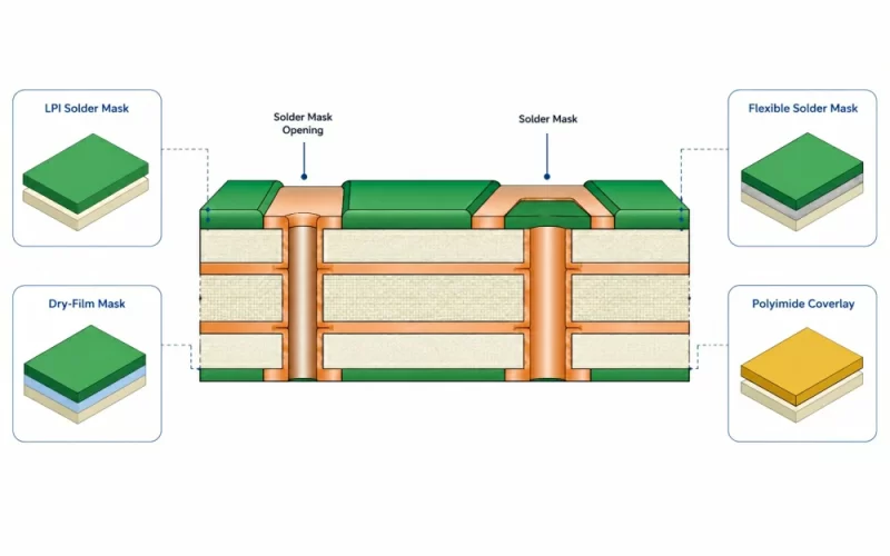
PCB solder mask materials shown in a cross-section with LPI, dry-film, flexible solder mask, and polyimide coverlay.

PCB solder mask materials are permanent polymer systems applied over copper to protect.

Standardized PCB module design and production risks

Choose flying probe testing for prototypes, changing designs, and high-mix builds. Choose in-circuit.

Leave a Reply

Your email address will not be published. Required fields are marked *