
In the constantly evolving world of PCB design and manufacturing, innovation often emerges from combining existing technologies to solve persistent engineering challenges. One such transformative innovation is the rigid-flex PCB—a hybrid circuit board that merges the structural stability of traditional rigid boards with the dynamic flexibility of bendable circuits. As electronic devices become smaller, more complex, and more reliable, understanding this technology is crucial for engineers and product developers. This comprehensive guide explores what rigid-flex PCBs are, their significant benefits, practical design tips for implementation, and their growing applications across cutting-edge industries.
What Exactly Is a Rigid-Flex PCB?
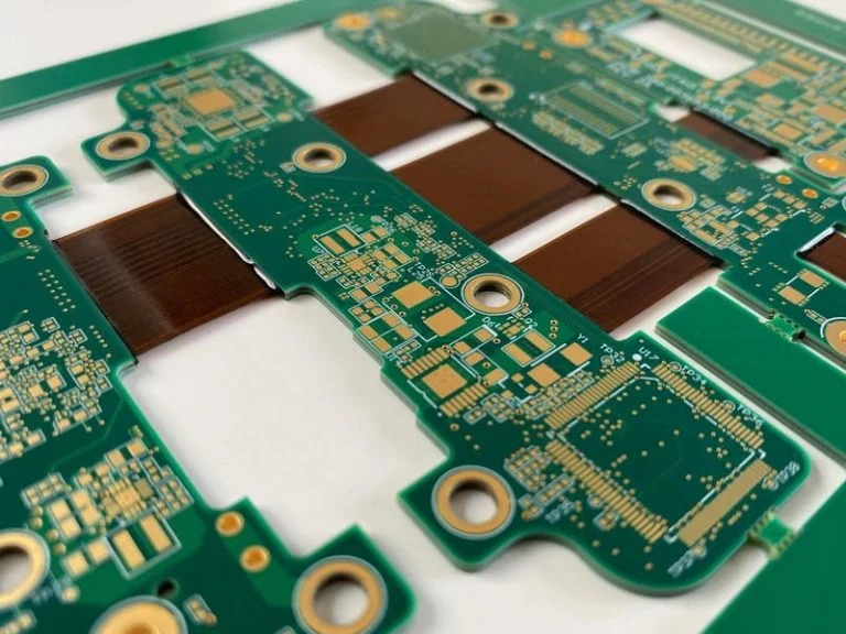
A rigid-flex PCB is an integrated circuit board structure that incorporates both rigid and flexible substrate materials laminated together into a single, cohesive unit. Unlike traditional assemblies that use connectors and cables to link separate rigid boards, a rigid-flex design creates a continuous, reliable connection through flexible layers that can bend, fold, or twist during use or installation.
Core Construction:
The typical rigid-flex PCB consists of multiple layers:
- Rigid Sections: Made from standard FR-4 material, these areas provide mechanical support for mounting components, connectors, and chassis attachment points.
- Flexible Sections: Composed of polyimide or similar flexible film (like Kapton), these thin, bendable layers contain the traces that connect the rigid areas.
- Transition Zones: The critical areas where the rigid and flexible materials meet, requiring careful design to ensure reliability.
This seamless integration eliminates discrete wiring and connectors, which are common points of failure in conventional electronic assemblies.
Key Benefits of Rigid-Flex PCB Technology
The adoption of rigid-flex PCBs offers compelling advantages that address multiple challenges in modern electronics:
Enhanced Reliability and Durability
The most significant benefit is the dramatic improvement in reliability. By eliminating connectors, solder joints, and discrete wires—which account for a high percentage of electronic failures—rigid-flex designs create more robust systems. The flexible portions can withstand thousands to millions of bend cycles without failure when designed correctly, making them ideal for applications with constant motion or vibration.
Space and Weight Savings
Rigid-flex PCBs enable three-dimensional packaging, allowing designers to utilize unused space within enclosures. Flexible sections can fold around other components or conform to unique housing shapes. This consolidation often reduces the total board area by 30-50% and significantly cuts weight—a critical factor in aerospace, automotive, and portable devices.
Simplified Assembly and Reduced Costs
While the initial PCB fabrication cost may be higher, the total system cost often decreases. Assembly is streamlined into a single process, reducing labor, eliminating connector procurement and installation, and minimizing opportunities for assembly errors. The consolidated design also simplifies supply chain management.
Improved Signal Integrity and EMI Performance
High-speed signals benefit from continuous impedance-controlled traces without the discontinuities introduced by connectors. The reduced need for external cabling also minimizes electromagnetic interference (EMI) and crosstalk, as signals remain within the controlled environment of the board stackup.
Design Freedom and Innovation Enablement
Rigid-flex technology enables previously impossible form factors. Devices can now be curved, folded, or designed to move dynamically while maintaining electrical connectivity. This has been instrumental in the development of modern wearable devices, medical implants, and compact military systems.

Essential Rigid-Flex PCB Design Tips and Guidelines
Successfully implementing rigid-flex technology requires attention to specific design considerations:
Understand Your Flexibility Requirements
- Static vs. Dynamic Flex: Determine if the flexible section will bend only during installation (static) or repeatedly during operation (dynamic). Dynamic applications require more robust design with tighter bend radius rules.
- Bend Radius: As a fundamental rule, maintain a minimum bend radius of at least 10 times the total flex layer thickness for single-bend applications, and larger for dynamic flexing. Violating this can cause copper cracking and delamination.
Optimize Layer Stackup and Transitions
Work closely with your PCB manufacturer during the stackup planning phase. Ensure symmetrical construction around the neutral bend axis in flexible areas to prevent stress concentration. In transition zones between rigid and flex areas, stagger the termination of rigid layers to create a gradual "teardrop" transition, reducing stress concentration.
Component Placement and Routing Guidelines
- Keep Components Off Flex Areas: Place all components and vias on rigid sections whenever possible. If components must be on flex areas, use specialized flex-grade components and reinforce with epoxy.
- Route Perpendicular to Bend: Traces in flexible sections should run perpendicular to the bend axis. Avoid placing traces parallel to the bend line near the outer radius where stress is highest.
- Use Curved Corners: All corners in the flex outline should have generous radii (minimum 1.5mm) rather than sharp 90-degree angles to prevent tearing.
Material Selection and Finish Considerations
- Keep Components Off Flex Areas: Place all components and vias on rigid sections whenever possible. If components must be on flex areas, use specialized flex-grade components and reinforce with epoxy.
- Route Perpendicular to Bend: Traces in flexible sections should run perpendicular to the bend axis. Avoid placing traces parallel to the bend line near the outer radius where stress is highest.
- Use Curved Corners: All corners in the flex outline should have generous radii (minimum 1.5mm) rather than sharp 90-degree angles to prevent tearing.
Incorporate Strain Relief and Stiffeners
For areas where the flex section connects to connectors or interfaces with moving parts, add mechanical strain relief. This can include epoxy dots, specialized flex connectors, or added stiffeners (usually FR-4 or polyimide patches) to distribute stress.

Key Applications of Rigid-Flex PCBs
The unique advantages of rigid-flex technology have made it indispensable in several high-tech sectors:
Aerospace and Defense:
Avionics systems, satellite components, and military communications equipment benefit from the weight reduction, high reliability in extreme environments, and resistance to vibration and shock.
Medical Devices:
From hearing aids and pacemakers to advanced imaging equipment and surgical tools, rigid-flex PCBs enable miniaturization and reliability in life-critical applications where space is limited and sterilization is required.
Consumer Electronics:
Modern smartphones, cameras, and wearable devices (like smartwatches and fitness trackers) use rigid-flex boards to achieve compact, lightweight designs with moving parts (e.g., folding phones, rotating cameras).
Automotive Electronics:
Advanced driver assistance systems (ADAS), infotainment consoles, and sensor modules increasingly use rigid-flex designs to withstand vehicle vibration, temperature extremes, and space constraints.
Industrial and IoT Equipment:
Robotics, industrial sensors, and Internet of Things devices utilize rigid-flex boards for reliable operation in harsh environments and for enabling innovative form factors.
Conclusion: Embracing the Hybrid Future
Rigid-flex PCB technology represents a significant evolution in circuit design, offering solutions to the conflicting demands of miniaturization, reliability, and performance. While the design and manufacturing process requires specialized knowledge and collaboration with experienced fabricators, the benefits often justify the investment for appropriate applications.
As electronic products continue to push boundaries in size, functionality, and environmental resilience, rigid-flex technology will play an increasingly central role. By understanding its principles, benefits, and design considerations, engineers can leverage this powerful technology to create next-generation electronic devices that are more reliable, compact, and innovative than ever before.
For your next project requiring three-dimensional packaging, motion tolerance, or extreme space constraints, consider whether a rigid-flex PCB design might provide the elegant solution you need. Consult early with manufacturing partners to ensure your design is optimized for both performance and producibility.


