If you compare a 1.2mm vs 1.6mm PCB keyboard, the short answer is simple. Choose 1.2mm if you want more flex and a softer typing feel. Choose 1.6mm if you want stronger support, easier assembly, wider stabilizer support, and lower production risk.
PCB thickness affects more than feel. It can change stabilizer fit, hotswap socket stress, USB-C alignment, plate spacing, gasket compression, and case tolerance. At Weller PCB, we review PCB thickness as both a typing-feel choice and a manufacturing choice.
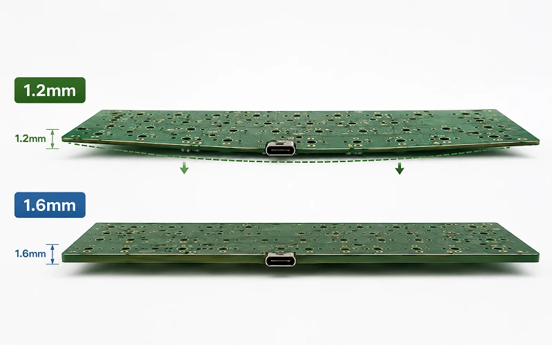
What Is the Difference Between 1.2 and 1.6 mm PCB?
The 0.4mm gap may look small, but it can affect the full keyboard build. It can change stabilizer fit, USB-C port height, gasket compression, plate-to-PCB spacing, and switch removal stress.
The 0.4mm gap may look small, but it can affect the full keyboard build. It can change stabilizer fit, USB-C port height, gasket compression, plate-to-PCB spacing, and switch removal stress.
If your keyboard uses USB-C, RGB, or dense routing, review practical PCB layout guidelines for electronics design before fabrication. A keyboard may look simple, but the PCB still needs careful mechanical and electrical planning.
| Factor | 1.2mm PCB | 1.6mm PCB |
|---|---|---|
| Feel | Softer and bouncier | Firmer and more solid |
| Flex | Higher | Lower |
| Stabilizers | Needs 1.2T stabilizers or shims | Works with most 1.6T stabilizers |
| Hotswap use | Needs stronger socket support | More forgiving |
| Best for | Gasket and flex builds | OEM and production builds |
How Thick Is 1.2 mm?
A 1.2 mm PCB is about 0.047 inches, or about 47 mils. A 1.6mm PCB is about 0.063 inches, or about 63 mils. So 1.6mm is thicker, and 1.2mm is thinner.
In PCB manufacturing, these numbers usually mean finished PCB thickness. Finished thickness includes FR-4 core, prepreg, copper, solder mask, and surface finish. Keyboard parts fit around this final board size, not only the core thickness.

What Is Standard PCB Thickness?
The most common standard PCB thickness is 1.6mm. Many PCB factories, component suppliers, and mechanical designers use it as the default size because it balances strength, cost, compatibility, and manufacturability.
A 1.2mm PCB is also common, but it is more specialized. It gives more flexibility and a thinner structure. This makes it useful for custom mechanical keyboards, compact electronics, and products where feel or space matters more than stiffness.
For controlled layer planning, review a 4-layer PCB stackup design guide before you choose thickness.

What Is the Best Thickness for PCB?
The best PCB thickness depends on the product. For a mechanical keyboard PCB, 1.2mm is better when flex is a core feature. 1.6mm is better when stability, assembly speed, and durability matter more.
| Use Case | Choice | Why |
|---|---|---|
| Gasket mount keyboard | 1.2mm | More flex |
| Beginner hotswap kit | 1.6mm | Better support |
| OEM production | 1.6mm | Lower risk |
| Premium flex-cut board | 1.2mm | Softer feel |
| Prototype testing | Test both | Feel is build-dependent |
Flex Cut vs Non Flex Cut PCB
A flex cut PCB has slots or cutouts that let the board bend more under typing force. A non flex cut PCB keeps more material, so it feels firmer and more stable.
A 1.2mm PCB with flex cuts can feel very soft and bouncy. A 1.6mm PCB with flex cuts can feel more controlled. Too much flex can increase stress around hotswap sockets, solder joints, and narrow PCB areas.
Plate material also changes the result. Aluminum feels firmer. Polycarbonate feels softer. FR-4 feels balanced. POM feels muted and flexible.
PCB Thickness Keyboard: Hotswap vs Soldered Builds

A hotswap keyboard PCB lets users change switches without soldering. This is convenient, but each switch change pushes force into the socket, pad, and board.
Kailh-Style Hotswap Socket Support
Kailh-style hotswap sockets can work on both 1.2mm and 1.6mm PCBs, but a thinner board needs more care. On a 1.2mm PCB, switch insertion force can bend the board more easily and stress socket legs, solder joints, and pads. On a 1.6mm PCB, the socket area usually moves less.
Always check the socket datasheet, footprint, and assembly rules before production. For a 1.2mm hotswap PCB, add back support under the socket area when the case allows it. Back support helps reduce bending during switch insertion and removal.
A soldered PCB has fewer socket stress problems, so a 1.2mm soldered board can work well if the case and plate support it properly.
What PCB Thickness Tolerance Should You Use?
The thickness tolerance of a 1.6 mm PCB depends on the manufacturer, material, stackup, layer count, and process. Many standard FR-4 boards use a tolerance around ±10%, but you should confirm the exact value with your supplier.
Recommended Tolerance for 1.2mm Keyboard PCBs
Use tighter finished thickness control when the design depends on stabilizer fit, USB-C height, or case compression. For a 1.2mm keyboard PCB, a practical target for tighter mechanical fit is often around ±0.10mm when the factory can support it. This is not a default rule for every PCB. It is a safer target for thin keyboard builds with tight parts.
A small thickness change can affect stabilizer fit, USB-C centering, plate spacing, gasket compression, hotswap socket seating, standoff height, and screw length.
Electrical Performance and Stackup

For a simple keyboard matrix, PCB thickness is usually not the main electrical risk. Trace layout, diode placement, MCU routing, and firmware support often matter more.
For advanced keyboards, stackup becomes more important. USB-C routing, RGB power, wireless modules, ESD protection, and EMI control all need attention. A 2-layer PCB works for many simple keyboards. A 4-layer PCB gives better ground planes and cleaner routing.
Surface finish also matters. ENIG gives flatter pads and better shelf life. Lead-free HASL costs less, but it is less flat. For premium hotswap keyboard PCBs, ENIG is often the better choice. You can compare both options in this guide to PCB surface finish HASL vs ENIG.
Manufacturing and Quality Control
A thinner board needs more careful manufacturing control. A 1.2mm PCB can warp more easily during fabrication, assembly, shipping, or storage. A 1.6mm PCB is stiffer and more stable.
Good production should check finished thickness, warpage, electrical performance, AOI results, solder mask registration, drill accuracy, and first article samples.
When Prototype Validation Is Required
Prototype validation becomes important when the keyboard uses a 1.2mm PCB, flex cuts, hotswap sockets, tight USB-C case openings, custom stabilizer cutouts, gasket mounting, or a new plate material. In these cases, build samples first and test stabilizer fit, socket strength, switch insertion force, switch removal force, USB-C alignment, case closing, typing feel, and sound.
At Weller PCB Manufacturing Company, we review keyboard PCBs as full systems. We check thickness, tolerance, FR-4 material, stackup, copper weight, surface finish, stabilizer cutouts, USB-C routing, RGB power distribution, panelization, and production risk.

Conclusion
The 1.2mm vs 1.6mm PCB keyboard choice depends on your goal. Choose 1.2mm for a softer, lighter, and more flexible typing feel. Choose 1.6mm for a stronger, firmer, and more production-safe design.
If you choose 1.2mm, use matched 1.2T stabilizers, tighter thickness control, good socket support, and prototype testing when the design has tight mechanical parts. Thickness is important, but you should also check flex cuts, plate material, case tolerance, stackup, surface finish, socket support, and production volume. Weller PCB can help you turn that choice into a manufacturable keyboard PCB specification. For project support, request instant quotes for PCBA solutions.
FAQ
Can I use 1.6T stabilizers on a 1.2mm PCB?
You can test them with shims, but 1.2T stabilizers are better for production.
Does a 1.2mm PCB always feel better?
No. It feels softer, but the final feel also depends on the plate, case, mount, foam, switches, and typing style.
Should I check the hotswap socket footprint?
Yes. Check the socket datasheet, PCB footprint, pad design, and assembly process before production.
When should I prototype before mass production?
Yes. Check the socket datasheet, PCB footprint, pad design, and assembly process before production.
Which PCB thickness is safer for first-time keyboard projects?
Yes. Check the socket datasheet, PCB footprint, pad design, and assembly process before production.


